Car amp circuit can be used for a quality used 4 tda2004 tda2004 stereo integrated amp that can provide 2 × 10 watts of power with an integrated bridge mono 20w power connection can be taken. Because it is the only source of supply voltage 12 volts from the battery supply can run with.
In addition to input 12v 2200uf 25v capacitor series addressed 2 of the coil in a relay output if you use the speaker delay circuit is more efficient.
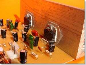
TDA2004 Car Amplifier Circuit

a stereo amplifier with 4 outputs, each 20W RMS. This amp has a stereo and 4 TDA2004 integrated, working entry two, to the right channel and amplify the signal to the right car doors, and two integrated amplify the left channel, similarly to send signal to the speakers of the left door. This amplifier is powered by 12 volts DC, can be used to amplify videorockolas of computer notebook (laptop), which are being used for picnics, connecting to the car battery.
TDA2004A Amplifier Car Radio

Low distortion. Low noise. High reliability of the chip and of the package with additional safety during operation thanks to protect.
Output ac short circuit to ground, Very inductive loads, Overrating chip temperature, Load dump voltage surge, Fortuitous open ground
Source: videorockola.com TDA2004 car amplifier schematic pcb files alternative link:


An Interesting Method for Printed Circuit Board Cardboard PCB
Method practicality questionable, but now the most appropriate category “Practical Information” will be earlier in the PCB about the making of articles I’ve shared now the easiest and cheapest method iron is happening with the new I met a brother of mine ever never crossed my mind a method I have used 🙂
Profession has nothing to do with electronics, but ingrained curiosity amp circuits because there is no experience of making PCBs is very difficult for him