A full-fledged stereo power amplifier with the TDA1517 chip. It is powered by single voltage, achieves 2×6W output power at 4 Ω load. The whole is designed as a small module with dimensions of 30mm × 38mm, which “will fit anywhere”.
The TDA1517 amplifier module can be used in self-made sound equipment or mounted in a factory device, e.g. in the place of a damaged power amplifier. It is also perfect as a computer power amplifier.
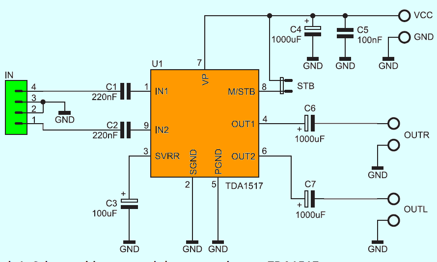
Figure 1 shows the schematic diagram of the module. The TDA1517 amplifier circuit contains short-circuit and thermal protection. The input signal supplied to the amplifier is supplied by capacitors C1 … C2. They prevent the constant power terminal from entering the input. The C3 capacitor filters the internal reference voltage, while the C4 and C5 capacitors filter the supply voltage, which should be in the range of 6 … 16 VDC.
The STB jumper allows you to turn on and off the amplifier that is still live. An advantage resulting from such a solution is that there is no need to use circuit breakers with high current capacity.
List of elements:
C1, C2: 220 nF
C3: 100 µF / 25 V
C5: 100 nF
C4, C6, C7: 1000 µF / 25 V
U1: TDA1517
VCC, OUTL, OUTR: ARK2 / 500 connector
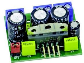
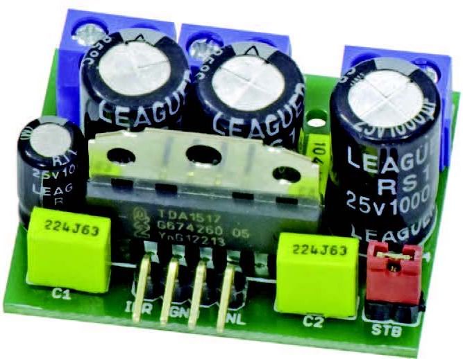
The location of the components on the amplifier’s circuit board is shown in Figure 2. Its installation is typical and should not cause any trouble.
TDA1517 Circuit Schematic
FILE DOWNLOAD LINK LIST (in TXT format): LINKS-26505b.zip


TDA1517 Circuit d’amplificateur miniature 2 × 6W
Un amplificateur de puissance stéréo à part entière avec la puce TDA1517. Il est alimenté par une tension unique, atteint une puissance de sortie de 2 × 6 W à une charge de 4 Ω. L’ensemble est conçu comme un petit module avec des dimensions de 30 mm × 38 mm, qui «s’adaptera n’importe où».
Le module amplificateur TDA1517 peut être utilisé dans un équipement de sonorisation ou monté dans un appareil d’usine, par ex. à la place d’un amplificateur de puissance endommagé. Il est également parfait comme amplificateur de puissance pour ordinateur.
La figure 1 montre le schéma de principe du module. Le circuit amplificateur TDA1517 contient une protection contre les courts-circuits et la protection thermique. Le signal d’entrée fourni à l’amplificateur est fourni par les condensateurs C1… C2. Ils empêchent la borne de puissance constante d’entrer dans l’entrée. Le condensateur C3 filtre la tension de référence interne, tandis que les condensateurs C4 et C5 filtrent la tension d’alimentation, qui doit être comprise entre 6 et 16 VDC.