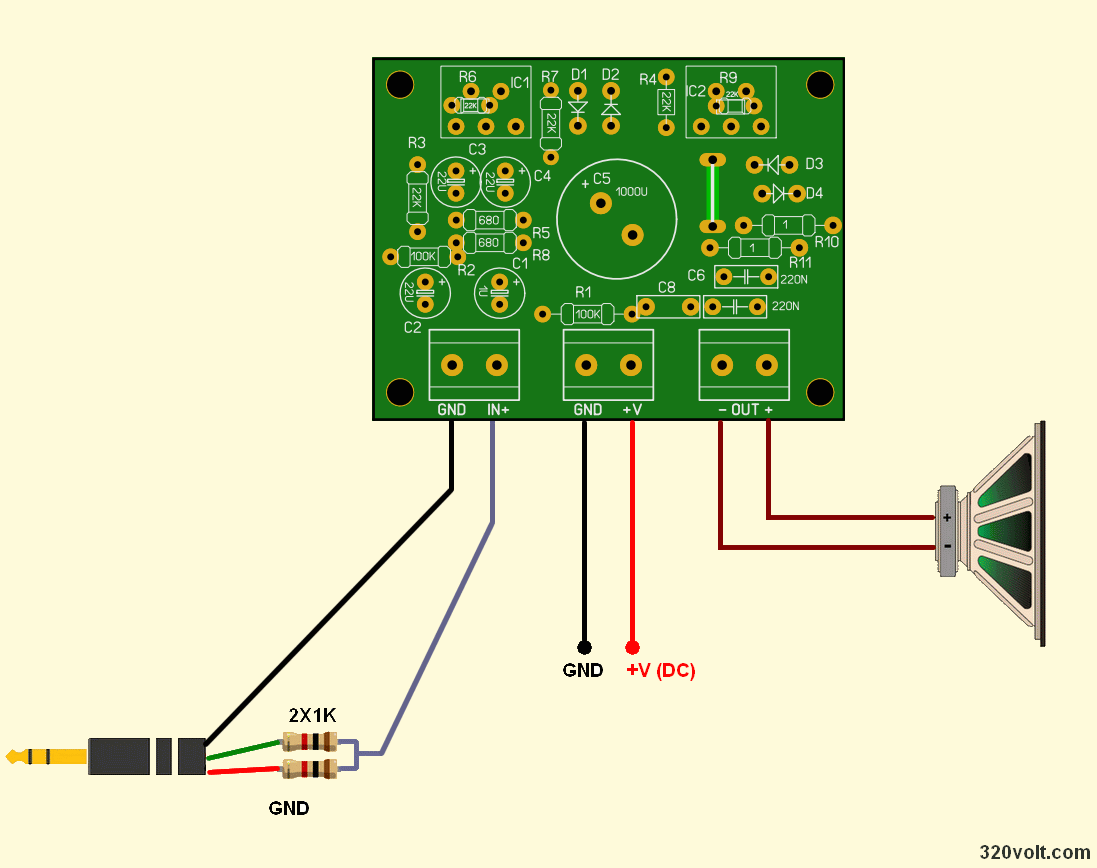
The TDA2030 Bridge amplifier can be used with a single source power supply. Working voltage DC 12V…. It is between 32V and can be operated with 12V battery, 24V battery, SMPS adapters or transformer power supply. (power of the voltage source according to the output power is 50W…60W)
The principle of the TDA2030 Bridge connection consists in connecting the load between the outputs of two power amplifiers whose output voltages are in antiphase. Therefore, the maximum voltage swing at the load can be twice as large compared to the case where the load is connected only between the output of the amplifier and ground, and thus it is theoretically possible to deliver four times more power to the load.
A bridge connection is advantageous in cases where we need to transfer as much power as possible to the load at a low supply voltage. Two monolithic amplifiers TDA2030 in bridge connection are used as power amplifiers.
TDA2030 Bridge Circuit Diagram
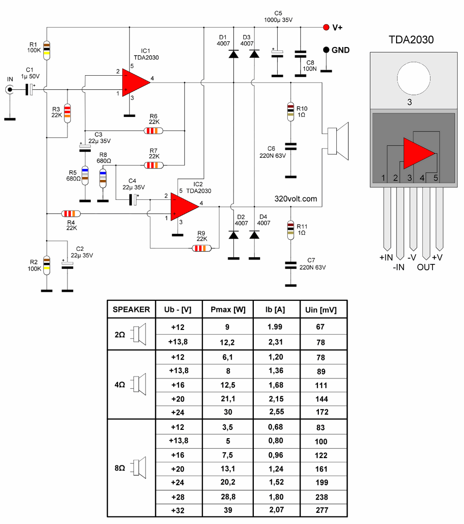
IC1 amplifies the input signal; IC2 is driven by the output signal from IC1 and the output signal is coupled to have opposite phase to the output signal of the IC. The speaker is connected between outputs IC1 and IC2. The frequency range of the amplifier is 10 Hz to 100 kHz (-3 dB) distortion is 0.2%.
The amplifier is designed with a single supply voltage Ub so that it can be powered from a car battery. Ub is fed to power terminals O3 and O6. A bias equal to half the supply voltage is applied to the non-inverting inputs IO1 and IO2 through resistors R3 and R4, and IO1 and IO2 are connected to act as signal followers with a gain for the dc voltage.
The bias voltage is obtained by the divider R1, R2, which reduces Ub by half. The center of the divider is blocked by capacitor C2 so that parasitic voltages from the power supply do not penetrate the input of the amplifier. The Nf input signal is fed from input terminals O1, O2 to the non-inverting input IO1 through coupling capacitor C1. The resistance of resistor R3 determines the input resistance of the 22 kW amplifier.
The voltage gain of the IC amplifier is determined by the negative feedback provided from the output of IC1 to the inverting input by the divider R6, R5 and C3. 1N4007 diodes connected to the output + and – lines are for protection purposes.
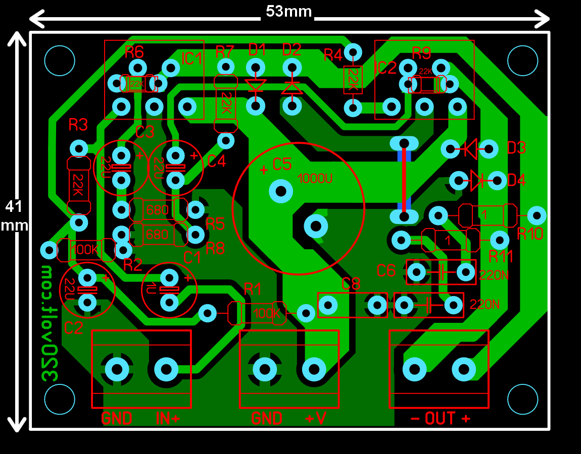
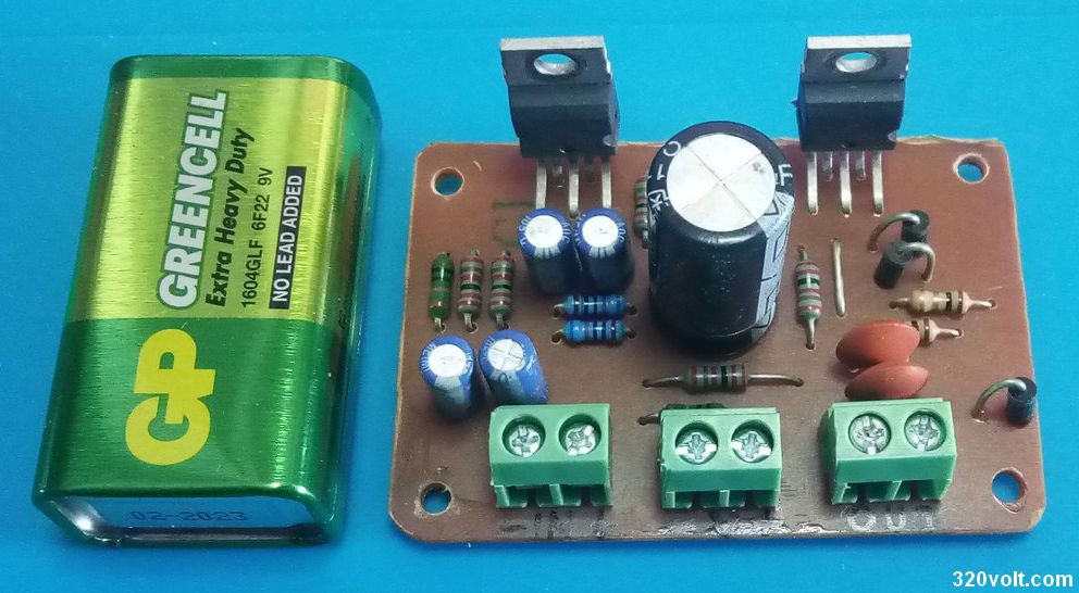
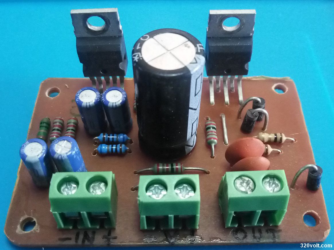
TDA2030 Bridge PCB design was prepared with Sprint layout 6, dimensions are 53x41mm single layer.