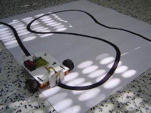
microchip Picless line tracking robot is a simple design to create a basic line tracking robot with CNY70 sensor and a few additional components instead of making a pic or arduino line following robot.
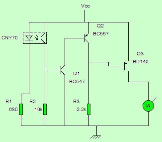
In the diagram shown, you can see how the circuit works, when the led of the CNY70 sensor reflects a reflective surface, such as the white color of the surface on which the viewer will move, the 680-ohm resistor is fed from the R1 light, the phototransistor in the CNY70 sensor lowers the resistance between the collector and the emitter, this It also conducts the current that causes the polarized transistor Q1 to be grounded from 10KΩ resistor to R2.
Q2 is used to reverse the signal so that when the motor sees white it is disabled and works when the sensor detects black.
The line-following robot circuit works with 4 1.5v batteries connected in series. The total voltage in the serial connection of the batteries is 6v.
Line following robot circuit diagram
A list of materials;
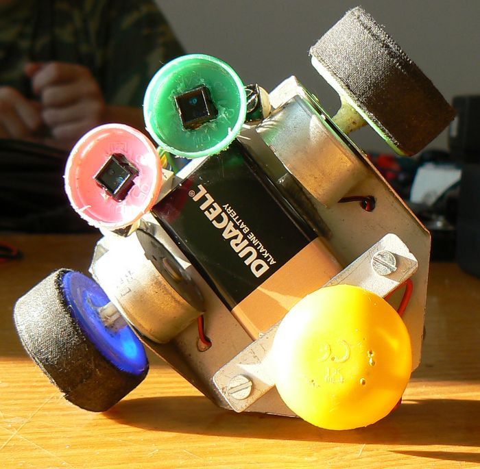
2x CNY70 sensor
2x BC547 transistor
BC557 Transistor
2x BD140 transistor
2x 680 Ohm resistor
2x 10k resistor
2x 2k2 resistor
1x R6 battery slot
1x slide switch
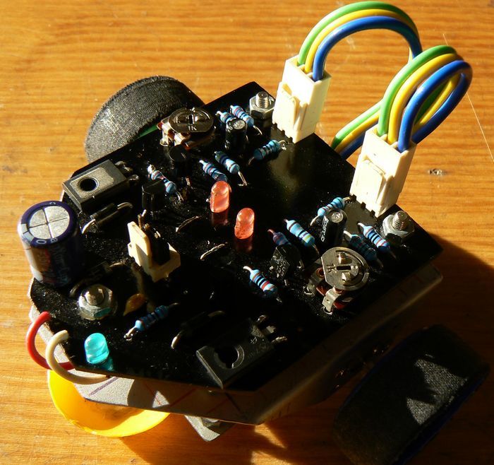
The robot circuit pcb drawing, which follows a slightly more advanced line, is powered by a 9v battery made for the robot body.
source: tecnosalva.com/robot-seguidor-l%C3%ADneas
FILE DOWNLOAD LINK LIST (in TXT format): LINKS-26373a.zip
Circuit robot suiveur de ligne simple
microchip Le robot de suivi de ligne Picless est une conception simple pour créer un robot de suivi de ligne de base avec un capteur CNY70 et quelques composants supplémentaires au lieu de créer un robot de suivi de ligne pic ou arduino.
Dans le diagramme illustré, vous pouvez voir comment fonctionne le circuit, lorsque la led du capteur CNY70 reflète une surface réfléchissante, telle que la couleur blanche de la surface sur laquelle le spectateur se déplacera, la résistance de 680 ohms est alimentée par le R1 la lumière, le phototransistor dans le capteur CNY70 abaisse la résistance entre le collecteur et l’émetteur, ce Il conduit également le courant qui provoque la mise à la terre du transistor polarisé Q1 de la résistance 10KΩ à R2.
Q2 est utilisé pour inverser le signal afin que lorsque le moteur voit le blanc, il soit désactivé et fonctionne lorsque le capteur détecte le noir.
Le circuit robot suiveur de ligne fonctionne avec 4 batteries de 1,5 V connectées en série. La tension totale dans la connexion série des batteries est de 6v.
Schéma de circuit du robot suivant la ligne