Remote control potentiometer PIC12F629 control protocol RC5 built on microcontroller
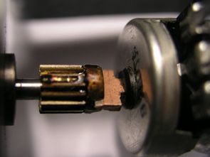
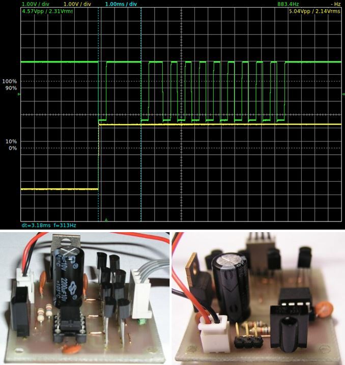
System An infrared receiver that controls the stepper motor mounted behind the potentiometer. The protocol is similar to the RC-5 protocol, using Manchester encoding is 13 bits long. After the first bit of two bits is skipped, the length of 1.06 ms is measured, followed by 10 bits – the start bit, 8 bit data and 1 bit apparently parity. The transition bit is as described in RC-5. When pressed, the driver first sends zeros (or ones?) To all data and then sends the appropriate code. While holding down the button, it only repeats the code at about 100 ms intervals.
The buyer learns by himself. Switching to Learning mode accepts and caches commands. If it gets the same code five times in a row, it stores it in EEPROM. There are two learning modes for amplification and attenuation.
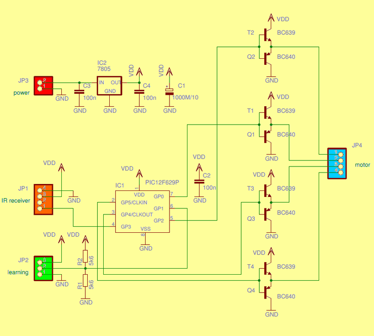
In the learning mode, it is necessary to show whether the new code has been registered. A stepper motor is used to signal. The motor draws about 400mA of power Therefore, the PIC12F629 outputs are powered by BC639 BC640 transistors.
The main program cycle only counts the pulse length to the stepper motor, then the output closes.
When a command is received, the infrared input edge triggers an interrupt. This is where almost everything happens. The command routine counts three and quarter bits and removes the next data from the input, then slowly removes the data until it collects a total of 8 data – these are returned to the input buffer. It was written for an area of selectable length as it originally planned a longer buffer. Therefore, a field that is one byte long is currently used. After receiving the command, the mode selection entry is scanned and evaluated
In run mode, the content of the input buffer is compared with the data in the EEPROM for each command and the command is executed when a match is found. Respectively, the appropriate combination is set at the outputs and the timer variables are set. This ends the cut. The timer in the main cycle of the program brings outputs to a halt.
In the learning mode, the newly received command is compared to the previous one. If there is a match, the successful trial counter is removed. When this counter reaches zero, the received command is written to the EEPROM in the location selected by the learning mode. If there is no match, the trial counter is set to the maximum number of trials and buffers for new and previous commands.
There are source asm, hex codes and scheme pcb drawings of the Controlled Potentiometer project.
Remote Controlled Potentiometer Circuit Diagram
Source: k15.kreteni.cz/ir_pot.php
FILE DOWNLOAD LINK LIST (in TXT format): LINKS-26532a.zip


Potentiomètre télécommandé
Potentiomètre de commande à distance Protocole de commande PIC12F629 RC5 construit sur microcontrôleur
Système Un récepteur infrarouge qui contrôle le moteur pas à pas monté derrière le potentiomètre. Le protocole est similaire au protocole RC-5, en utilisant le codage Manchester est de 13 bits de long. Une fois le premier bit de deux bits ignoré, la longueur de 1,06 ms est mesurée, suivie de 10 bits – le bit de début, les données de 8 bits et 1 bit apparemment de parité. Le bit de transition est tel que décrit dans RC-5. Lorsqu’il est enfoncé, le pilote envoie d’abord des zéros (ou des uns?) À toutes les données, puis envoie le code approprié. Tout en maintenant le bouton enfoncé, il ne répète le code qu’à des intervalles d’environ 100 ms.
L’acheteur apprend par lui-même. Le passage en mode d’apprentissage accepte et met en cache les commandes. S’il obtient le même code cinq fois de suite, il le stocke dans l’EEPROM. Il existe deux modes d’apprentissage pour l’amplification et l’atténuation.
En mode apprentissage, il est nécessaire de montrer si le nouveau code a été enregistré. Un moteur pas à pas est utilisé pour signaler. Le moteur consomme environ 400mA de puissance Par conséquent, les sorties PIC12F629 sont alimentées par des transistors BC639 BC640.
Le cycle de programme principal ne compte que la longueur d’impulsion du moteur pas à pas, puis la sortie se ferme.