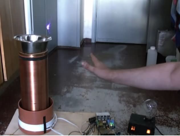
Previously I shared the quality Tesla Coil Circuits in Solid State Tesla Coil. This tesla coil drive circuit is controlled by tesla bobini according to a slightly different sound signal. TL494 IR2110 IGBT Tesla coil control doing a kind of tesla vu-meter or vu-tesla control can be controlled by motorda instead of high power PWM cycle tesla coil …
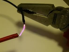
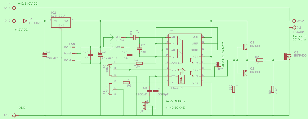
The first tesla coil driver circuit used old tube TV or monitor EHT high voltage transformer. EHT transformer is already used in many high voltage spark project. There is ready high voltage winding. In the first version IR2110 unused TL494 output is powered by BD139, BD140 transistors and IRFP660 MOSFET is driven. Frequency range between 10kHz ….. 180kHz
TL494 Tesla Coil Drive Circuit Diagram
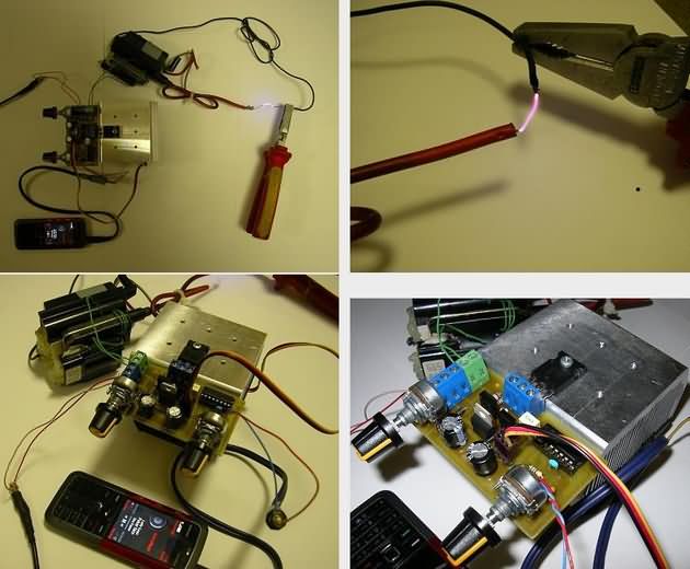
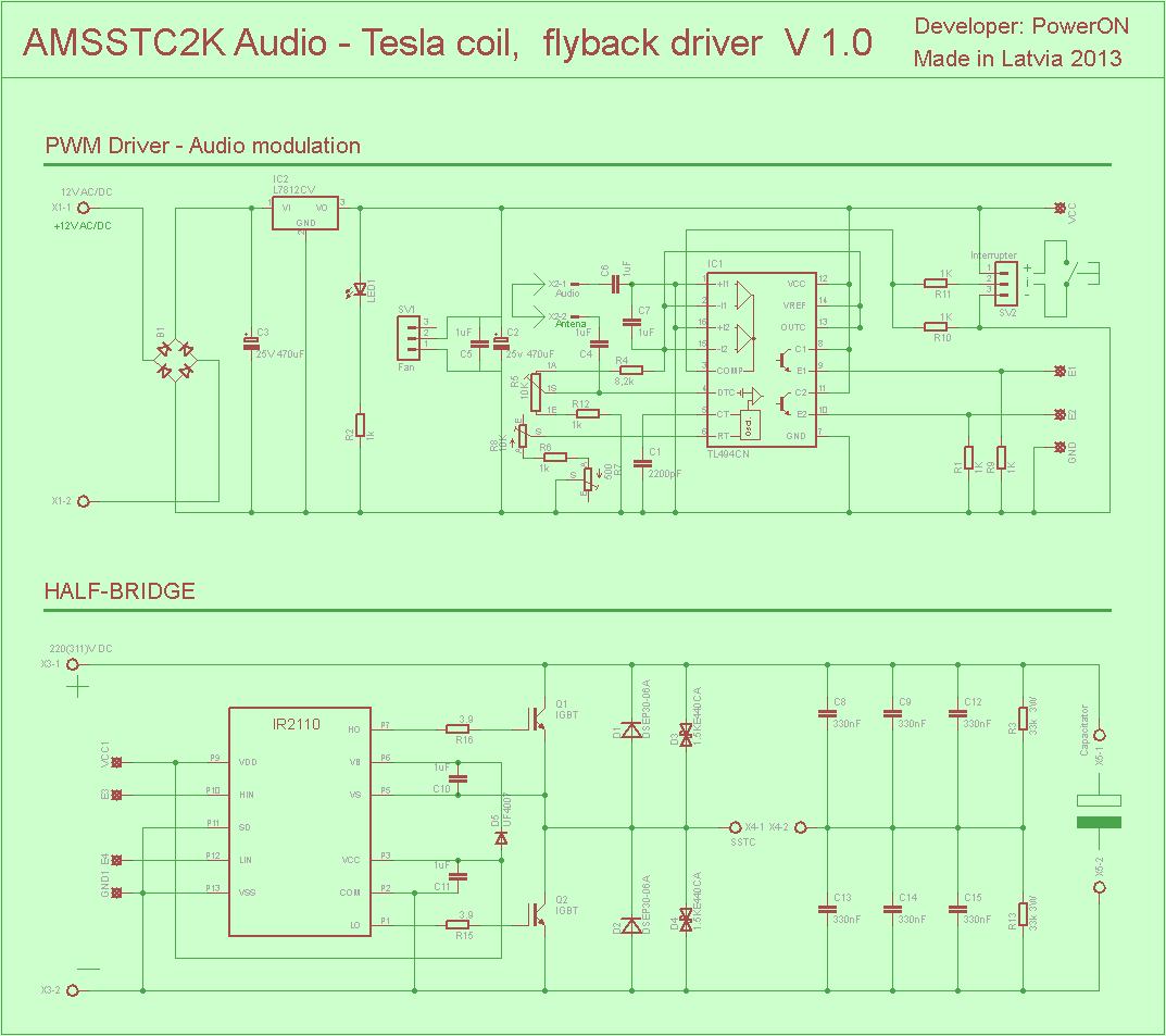
In the second version, this work, which is a big tesla bobbin, is a buss but it gets bigger spark. The power transistors used IR2110 MOSFET driver instead of transistor to enhance the output of TL494 IGBT (instead of IRFP054N can be used) spark grows in cost as the size grows …
TL494 IR2110 Tesla Coil Drive Circuit Schematic
CAUTION Tesla coils generate high voltage Be careful with capacitor connections + – If you reverse polarity, there may be large explosions at high voltage Fuse Power Line, use protective goggles before operating the circuit
Source: helfaforums.lv
FILE DOWNLOAD LINK LIST (in TXT format): LINKS-25951.zip


Zuvor teilte ich die Qualität Tesla Coil Circuits in Solid State Tesla Coil. Diese Tesla-Spulen-Treiberschaltung wird von Tesla Bobini entsprechend einem etwas anderen Schallsignal gesteuert. TL494 IR2110 IGBT Tesla Spulensteuerung, die eine Art Tesla vu-Meter oder vu-tesla Kontrolle durchführt, kann durch mordorda anstelle von PWM Zyklus tesla Spule der hohen Leistung … gesteuert werden
Die erste Tesla-Spule Treiberschaltung verwendet alte Röhre TV oder Monitor EHT Hochspannungstransformator. EHT-Transformator wird bereits in vielen Hochspannungsfunkenprojekten verwendet. Es gibt eine Hochspannungswicklung. In der ersten Version IR2110 wird unbenutzter TL494-Ausgang von BD139, BD140-Transistoren und IRFP660-MOSFET angesteuert. Frequenzbereich zwischen 10 kHz … 180 kHz
Arduino External Circuit Connection Charts
Arduino External Circuit Connection Charts
Arduino transistors, LEDs, motors, MOSFETs, various electronic components, circuit connection diagrams that will be of great use for Arduino projects, Arduino circuits or those who are new to Arduino programming … Circuit diagrams are simple to understand Detailed studies on the color codes of the resistors used in Arduino circuit connections ….
Arduino Connection Diagram List
Arduino Button GND connection, Button 5V connection, Button 12V connection, Built-in pullup, Using potentiometer, Photoresistor, Optocoupler inputs
Arduino Led, Lamp, Dual LEDs, Dual Color LED Connections, Arduino Relay, Mosfet, Buzzer, Sound Amplifier Connections, Arduino Triac, Speaker Connections, Arduino DC Motor, RGB Led Strip Led, Encoder Connections
Bidirectional Voltage Level Converter 3.3V to 5V, Bidirectional Voltage Level Transformer 3.3V to 5V with TTL / CMOS converter, TTL / CMOS converter (6 inputs / outputs) with voltage divider,
Arduino Microphone, Arduino Servo Motor Connections, Arduino Port Replication, 7 Segment Use, Arduino 7 Segment (Common Anode), Multiplexer, LED Array
Arduino LCD HITACHI 44780, Arduino I2C with an LCD HITACHI 44780, Arduino NOKIA LCD (Basic) with 7 segments use with Arduino MAX7221 (Common Anode)
Arduino Unipolar stepper motor drive (Basic 1), Arduino A Bipolar stepper motor drive (Basic 1), Graphical LCD connection via Arduino I2C
Arduino SD Card, Simple 3.3V Power Supply Connection, Arduino Temperature Sensor (LM35), RTC (DS1307), Video, VGA Connection
Arduino Keypad, PS2 Keyboard Connections, Arduino IR Receiver, IR Transmitter Link, Arduino MIDI Interface, Multiple Buttons Using 1 Analog Input
Digital Temperature Sensor (DS18B20), Simple Rain Sensor with Arduino, AC input, Port Expander (PCF8574xx), Shift (74HC595), Motor Drive (L298), Stepper Drive (L293)
EEPROM connection via I2C, Arduino Distance Sensor, Digital Potentiometer (MCP4161), DAC (MCP4921)
RS485 Node, DMX Controller (Basic), Resistor Color Codes, Ceramic Capacitor Codes, Polyester Film-Mylar Capacitor Code, Push Button Default, Simple Rescue, Rotary Encoder
Arduino Logical Analyzer, Current Sensitivity, Arduino Component Tester (Basic), Simple Transistor Comparison Table
Example Arduino Connection Schemes
VU-mètre PWM Tesla Audio IR2110 TL494
Auparavant, je partageais la qualité des circuits de bobines Tesla dans la bobine Tesla à semi-conducteurs. Ce circuit de commande de bobine tesla est contrôlé par tesla bobini en fonction d’un signal sonore légèrement différent. TL494 IR2110 Contrôle de bobine Tesla IGBT faisant une sorte de contrôle tesla vu-mètre ou vu-tesla peut être contrôlé par motorda au lieu d’une bobine tesla à cycle PWM haute puissance…
Le premier circuit pilote de bobine tesla utilisait un vieux téléviseur à tube ou un transformateur haute tension EHT à écran. Le transformateur EHT est déjà utilisé dans de nombreux projets d’étincelles haute tension. L’enroulement haute tension est prêt. Dans la première version IR2110, la sortie TL494 inutilisée est alimentée par BD139, les transistors BD140 et le MOSFET IRFP660 est piloté. Gamme de fréquences entre 10kHz… .. 180kHz