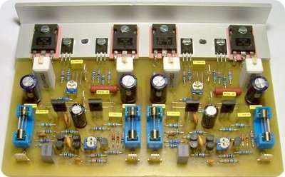
250W 500W Hifi Amplifier Circuits
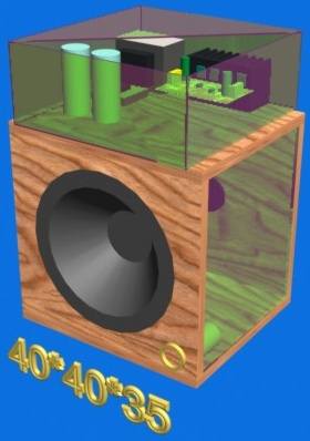
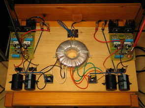
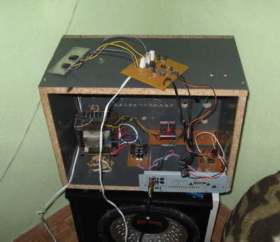
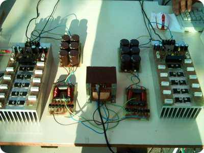
Prepared by: Tamircihasan 500w and 250w hifi amplifier for open space sound. Friends, the circuit is a circuit circulating in the market, but I made some changes on this circuit…
2SC5200 BJT transistor amplifier circuits, Mosfet transistor amplifier circuits 20w ……1000w, 2200w various power transistor amplifier projects
Prepared by: Tamircihasan 500w and 250w hifi amplifier for open space sound. Friends, the circuit is a circuit circulating in the market, but I made some changes on this circuit…
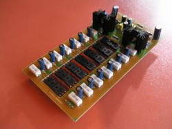
Circuit 8Ω Speaker with 100w rms 4Ω speaker and 200w rms power supply voltage 2x32V 2x40V used mosfets 4x IRF540 4x IRFP360 MOSFET transistor 100Wrms 8 ohm or 200Wrms 4..
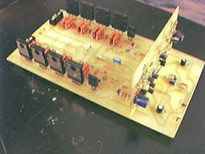
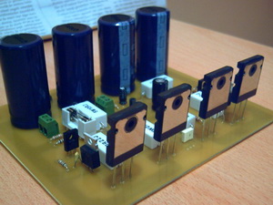
MJL21193 MJL21194 transistor 100 watts Hi-Fi Amplifier Circuit DC + -36 volts symmetrical supply is working with circuit diagrams and sprint layout prepared by the PCB drawing there. Lay uzntıl..
value can be between 40-50 mA bias current. potentiometer circuit upfront with it, but I did my ear again setting potentiometer at the point I left the clean sound. though..
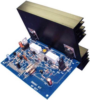
A quality amplifier circuit with low distortion, high sensitivity, output short circuit protection, delivering 100W of power. Amplifier Circuit works with a symmetrical +-40 VDC power supply and draws a..
N-channel IRFP260, IRFP450, IRFP240, IRF840 Mosfet Series with high quality power amp circuits have all the details (in English), especially in the picture 🙂 I liked TO220 and TO247 Cases..
The cost is high 🙂 output stage 14 (IRFP240 IRFP9240) Total Supply voltage MOSFETs used quite high +92 V-92V Be Careful The 800 Watt AV amplifier is based on My..
Quality pcb printed circuit design with two amp circuit I share 180 watt amp circuits used in power output transistors 2sa1943 2sc5200 supply voltage + -45 volts DC P-CAD 2001..
1000 watts power quality have a design output stage 6 irfp9240 (P-Channel) and 6 irfp240 (N-Channel) used the audio input section of the lf411 JFET input a quality op-amp opamp..
System 500W RMS at 4 ohm 620W RMS power gives 2Ω, 4Ω 500W RMS, 8Ω 380W RMS Circuit of the original scheme 8 MOSFETs used and 4Ω 400W writes 2Ω..