Tag: power electronic projects
Battery Discharge Protection Circuit
A simple battery discharge protection circuit implemented with TL431, BC557 transistors and a small number of resistors. The power line is controlled with an N-Channel MOSFET instead of a relay, so its current consumption is lower than the relay. The protection circuit triggers the MOSFET and gives output around 13.6V, and cuts off the output…
12V DC to 24V DC
Switch Mode Power Supply Transformer Tester
The SMPS Transformer tester is an inexpensive and effective way to test any high Q inductive component. The flyback is particularly useful for performing a quick check on line output transformers and other high frequency wound components such as bias yoke windings and SMPS transformers. Various measurements have shown that SMPS transformers can detect at…
Lion Battery Box Converter for Ni-MH Battery Drills
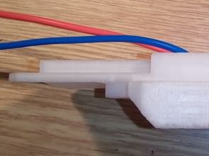
3D drawings of the old generation Ni-MH Battery Drills and the new generation Lion battery used drills with battery pack and box and holder apparatus Battery holders have .stl files for 3D printer. Battery converter 3D drawing printed on the stand from ABS, 1.2 mm thick and 30% filled. After printing, it was dipped in…
Battery Balancer LifePO4 Li-ion
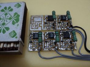
Battery balancer circuit is designed to control the charge thresholds of LifePO4 and Li-ion batteries. You can use it on Li-ion and LifePO4 batteries by changing 2 resistor values on the balancer. By adding transistor T1 and resistor R5 to the circuit, it was possible to convert TL431 into a Schmitt trigger. The divider R3,…
Advanced Charger Circuit
The purpose of the Charger is to overcome some of the limitations of the basic charger and offer users more flexibility. The advanced charger is based on similar hardware to the basic charger. The main differences are in the management of charge/discharge profiles, which can now be entered “locally” and without computer support. Differences from…
Active Cooling System for LED Lighting
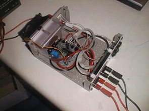
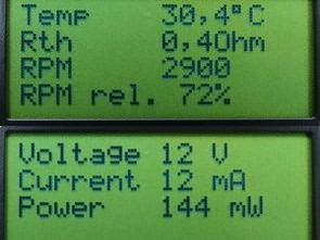
This project is about the design and subsequent implementation of independently operating active cooling for LED components. Its basis is a 12V fan used for efficient heat removal. ATMega16 microcontroller was used as the control element. A circuit that effectively and appropriately meets the current cooling needs of the LED module using external sensors, increasing…
Hot Glue Gun Booster Circuit
Hakko 907 Soldering Iron Control Circuit Arduino Nano
The Hakko 907 Soldering station is built on Arduino Nano, so you won’t need a programmer and various adapters for it again. The circuit has minimal parts and requires no adjustments. Hakko 907 soldering iron circuit has been used for about 5 years and has never caused any problems. Hakko 907 Driver Circuit Features: Designed…
