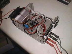
The purpose of the Charger is to overcome some of the limitations of the basic charger and offer users more flexibility. The advanced charger is based on similar hardware to the basic charger. The main differences are in the management of charge/discharge profiles, which can now be entered “locally” and without computer support.
Differences from basic charger
All parameters for charging and discharging can be entered directly into the charger.
PC is only useful for PIC16F876A software update and output graphics drawing.
A second P-channel mosfet is added for charging current up to 10A or in case there is no self-powering diode.
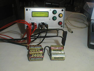
Display 16×2-line LCD display
There are up to 7 different charge/discharge profiles.
Batteries can be charged, discharged or cycled (charge after discharge)
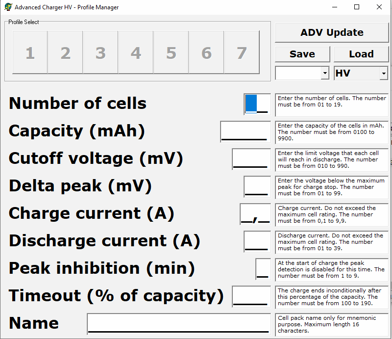
Parameters for each battery profile:
Number of cells (1 to 7)
Cell capacity (useful for automatic timeout calculation)
Cut-off voltage per cell
Delta peak per cell
Charging current (up to 10A or 5A plus diode)
Discharge current (up to 30A)
Peak control inhibition
Timeout as a function of cell capacity.
Support for constant voltage supply (motor test) with adjustable output
Fast current control (200Hz) and low noise values (1mV resolution for batteries)
Display during charging current, voltage, peak voltage, delta peak, capacity, time
Display during discharge of current, voltage, peak voltage, cut-off, capacity, time
Audible warning for end of operation signal
Automatic recovery in case of power supply failure
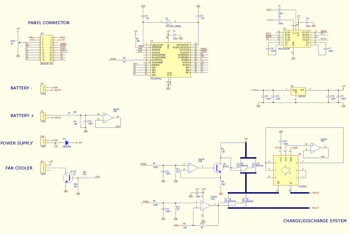
Advanced Charger Circuit Diagram


Hello, thank you for this circuit.
Can i use AVR series ( Atmega 16,32…) instead of PIC16F876A ? Or can it be customized to use with atmega32? Like the imax b6 charger.
Thanks.