The Hakko 907 Soldering station is built on Arduino Nano, so you won’t need a programmer and various adapters for it again. The circuit has minimal parts and requires no adjustments. Hakko 907 soldering iron circuit has been used for about 5 years and has never caused any problems.
Hakko 907 Driver Circuit Features:
Designed for Hakko 907 soldering irons (can be cloned)
Temperature range: 27°C–525°C
Warm-up time: 25–37 sec (325°C)
Recommended power supply: 24V, 3A
Power: 50W (average)
Ordinary soldering irons have disadvantages: The soldering iron needs 7-15 minutes to warm up before soldering. These soldering irons will continue to operate at maximum temperature after heating. In some cases, prolonged contact with these soldering irons can damage electronic components.
Digital Soldering Irons
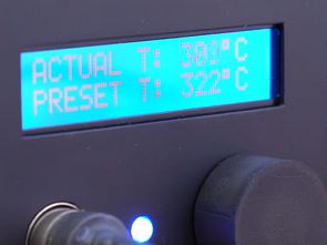
Digital soldering iron is very similar to Dimmer soldering iron, but everything is automated using a PID system. Simply put, an automatic electronic soldering station control system constantly checks, adjusts the set temperature. When the system detects that the soldering iron tip temperature is below the set temperature, it increases the power required to heat the tip.
When the soldering iron temperature is higher than the set temperature, its power will be turned off, causing the temperature to drop. The system accomplishes this very quickly by constantly turning the soldering iron heating element on and off to keep the temperature at the tip constant. Therefore, the warm-up time in digital soldering stations is significantly reduced.
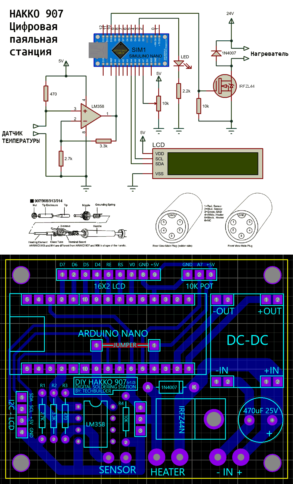
Digital Soldering Station Circuit Diagram
Required materials for Hakko 907 board:
- Soldering iron Hakko 907
- Arduino Nano
- Buck Converter MP2303 module
- 5-pin DIN female connector
- DC Jack 2.1mm
- Power supply 24 V, 3 A
- LCD 16X2 (with I2C driver)
- LM358 Op amp
- IRLZ44N Mosfet transistor
- 470uF 25V Capacitor
- 470Ohm 1/4W Resistor
- 2.7kOhm 1/4W Resistor
- 3.3kOhm 1/4W Resistor
- 10kOhm 1/4W Resistor
- 10kOhm Potentiometer
There is a heating element with a temperature sensor inside the Hakko 907 soldering iron. Both are coated with ceramic material. A heating element is a coil that produces heat when electricity is applied. The temperature sensor, on the other hand, is a thermistor. The thermistor is like a resistor: as the temperature changes, its resistance changes.
Hakko does not provide information about the thermistor inside the heating elements. Therefore, while heating the thermistor, the change in resistance was recorded and its value was learned.
A simple N-channel MOSFET controlled by the IRFZL44 logic level was used as the switching element in the project. It acts as a digital switch to power the heating element. A non-inverting op-amp (LM358) is used to amplify and scale the small voltages produced by the coupled voltage divider thermistor. The 10k potentiometer is used for temperature control and the LED is an indicator that I wired and programmed into the project to display whether the heating element is active or not.
The soldering station can be operated from any power source with an output voltage of 24V and a current of 3A. You can use a power supply from a laptop with an output voltage of 18V and a current of 2.5A, but the heating time of the soldering iron will increase to 37 seconds. In addition to the PCB and Arduino code files, there is also a “Temp, Resistance, ADC Data” XLSX file.


