A hot silicone gun was used extensively for a contract job. Since it did not heat up quickly, I solved the problem with a simple rectifier circuit. It was used for about 2 weeks and it did not cause any problems, but constant exposure of the resistor to high voltage may cause problems. I decided that it would be healthier to add a simple release delay circuit.
The first circuit is rectified to 220VAC with a simple bridge diode and filtered with a 22uf 400v capacitor. When the resistance is cold, the DC voltage is around 280V. As the silicone tank heats up, the voltage rises to 310V. We had no problems with this system, but it would be better to provide 220VAC after the silicone gun warms up. To increase the release time, you should increase the value of the 470K resistor.
555 integrated circuit was used for the release delay circuit, and power for the relay was provided by regulating 220AC directly. I used the Transformerless Power Supply 220VAC 12VDC 100mA circuit that I shared before.
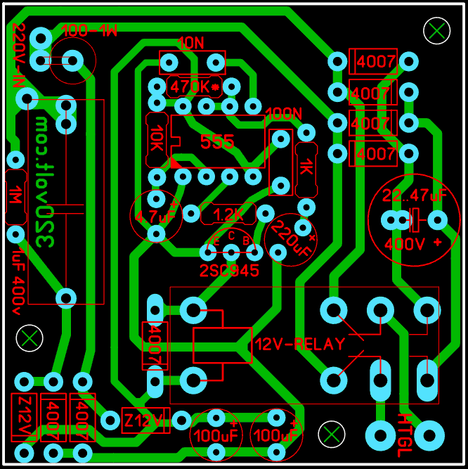
I prepared the PCB design of the circuit with Sprint Layout 6, its dimensions are 5x5cm. Checked but not tested
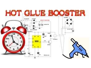
Hot Glue Gun Booster Circuit diagram