This project is about the design and subsequent implementation of independently operating active cooling for LED components. Its basis is a 12V fan used for efficient heat removal. ATMega16 microcontroller was used as the control element. A circuit that effectively and appropriately meets the current cooling needs of the LED module using external sensors, increasing the life and reliability of the LED lighting system.
The advantages of lighting with LEDs include higher mechanical resistance, constant brightness throughout the life of the diodes, lower electricity consumption, smaller dimensions. On the other hand, its disadvantages include the point character of the light and its thermal properties, where only a quarter of the energy is converted into light. The rest is waste heat. In addition to being a light source, LED is also a heat source that must be dissipated.
Cooling occurs actively with the air flow created by the fan; in this case, passive cooling will be insufficient. The fan is operated only when necessary. According to the output signal from the thermistor, the device decides whether to run the fan or adjust the speed. A fan, which is generally used to cool the PC, is used in this project.
Thanks to the Hall sensor inside, it is possible to monitor the rotation speed of the fan with an external device called TACHO signal. It works with 12V DC, the maximum number of revolutions is 4000 per minute. Two of the three wires are power. The third is used to measure revolutions (the frequency of the signal is inversely proportional to revolutions). A rectangular signal with 50% alternation is output during rotation. Fan speed control is implemented using PWM. With the PWM signal, an N-type MOSFET transistor is driven.
NTC thermistor is connected to ATMega16 microcontroller for temperature measurement. Tension is detected at the nodes of the bridge. The data required for further decision making can thus be obtained with a ten-bit A/D converter.
A 100kΩ resistive thermistor was used in the project (this value is valid at 25°C). The characteristic of the thermistor is generally non-linear. If we connect a resistor (50kΩ) in series, the voltage curve becomes linear with temperature (temperature calculation from two linear equations approximated by a dashed solid line – each for a different temperature range). These values were chosen to ensure that the measured voltages are in reasonable proportion to the reference voltage. This way the entire range of the transducer is used. The thermistor is connected together with three other 50kΩ resistors in a Wheatstone bridge. Additionally, a capacitor is connected in parallel with the thermistor, the voltage on it will be more stable.
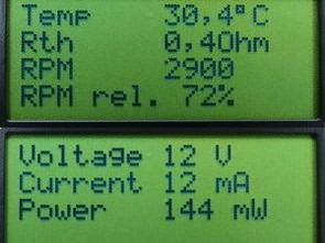
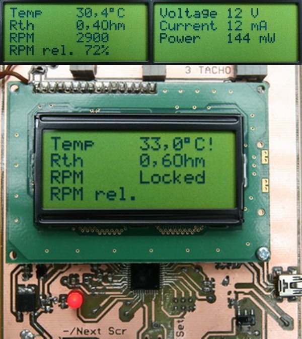
Screenshots of the device
Screen number 1: Display of temperature, resistance and speeds.
Screen number 2: Display of voltage, current and fan power.
Display number 3: Displayed when the fan is blocked, including the LED indicator.
Program Description Start – parameter setting
After initialization, the initialization function (void init(void)) is started first, starting communication with the LCD screen and displaying the initial screen. When confirmed with the OK key, the screen for adjusting the power of the LED module is displayed, where the thermal resistance is calculated. + and – keys change adjustable values in the range of 0-255W in 1W steps. Once confirmed, fan speed measurement begins. The fan runs at full speed when this measurement is initiated by applying a constant high level to the PB3 pin from the start of the program.
The measured value appears on the screen after approximately 3 seconds and waits for confirmation. Then the ambient temperature and the desired temperature on the radiator are set. After another confirmation, the registers of the peripherals (A/D converter, counters, I/O pins) are set and the program then jumps into an endless loop.
Within this endless loop, the program continuously tests for an indication that the ATMega16 A/D conversion is complete and button presses to cycle through screens. If the conversion results of all channels are available, the program turns off the interrupt after the A/D conversion and tests whether it is on.
If so, a function is called to measure the fan speed. After this measurement is completed, a function is called that calculates the temperature of the thermistor and the thermal resistance of the cooler from the voltages measured at the inputs of the A/D converter. It also determines the speed (absolute and relative), voltage, current and power consumption of the fan when it is turned on. The calculation results are displayed on the LCD screen, including critical conditions (exceeding the permissible temperature of the heatsink, blocking of the fan, disconnection of the thermistor). The first two states are also indicated by a red LED due to their critical functions.
Cutting after A/D conversion is completed
Temperature change or Thermistor resistance is slow due to the speed of conversion, only one sample is recorded after a certain period of time. To eliminate inaccuracy, only the tenth sample starts recording after changing the channel. Noise and other induced random voltage fluctuations are eliminated by averaging 32 samples from each channel.
When sufficient sample is obtained, the channel is changed. When the fan is turned off, only the channels required for temperature measurement are used for measurement. Once a set of 32 samples is obtained for each channel in use, they are averaged and a flag is set to indicate the presence of valid data for further calculations. In a situation where the thermistor voltage exceeds 900, which is not possible with correct connection since it corresponds to the reference voltage, a flag is set indicating that the thermistor is connected incorrectly.
RPM measurement function
At startup, the measurement counter is reset. During a function call, three measurements are taken and their results averaged. To measure fan speed, a constant high level must be briefly applied to the PB3 control pin. Speed measurement cannot be performed while the PWM signal is applied. Therefore, the output is turned off using the PWM control register and the corresponding pin is set to a high level. Due to the inertia of the fan, its speed will increase only slightly during this time, but a rectangular signal will be produced at the TACHO output, the period of which can be easily measured.
Counter/Timer Capture unit 1 is used for this. The control registers are set so that the state of the counter is captured when a rising edge is detected and also the interrupt service is activated upon overflow. A loop is started within the function, waiting for an indication that the measurement is complete (variable data_ready_rpm).
As part of the interrupt handler after an edge is caught, the precision is changed to the falling edge and the state of the counter is stored in the initial variable. At the second interrupt, the state of the counter is recorded in the stop variable. The difference in the values of the start and stop variables gives the pulse length of the rectangular signal, which is one quarter of the fan speed period. Then the data_ready_rpm flag is set, the counter value is reduced and the next measurement is waited. Pulse length measurement is repeated 3 times and the result is averaged.
If edge capture does not occur, when counter1 overflows, an interrupt handler is fired and the measure is returned with a value of zero. This means the fan is not spinning and the function returns a zero RPM value. After the measurement is finished, PWM output starts again. The function directly returns the calculated revolutions. The last code of the function deals with situations where the speed changes rapidly during fan startup and incorrect values may be displayed.
Calculation function
The temperature in the thermistor is calculated by the difference of node voltages in the bridge, and the temperature dependence of the thermistor resistance is approximated by a dashed solid line. Based on the calculated parameters (temperature and parameters entered by the user at the beginning of the measurement, such as ambient temperature and module power), the thermal resistance is calculated. The cooling control itself is also performed as part of the calculations. The temperature value is tested and the fan is started when the specified value is exceeded. The speed is controlled by the algorithm described below. If the temperature drops below the set temperature, the fan will be turned off. Symptoms of critical situations are also tested. These include blocking the fan (zero speed with the fan on) and exceeding the maximum temperature.
Speed control algorithm for temperature stabilization
Speed control takes place within the calculation function. The algorithm is executed only when the fan is on. First of all, the temperature change compared to the previous measurement is integrated for 32 measurements and recorded in the delta_temperature variable. This gives the trend of temperature over time (i.e. whether the temperature is rising or not) and also filters out small temperature changes in the opposite direction as the overall trend.
Once the integration is complete, the algorithm divides based on whether the current temperature is higher or lower than the specified temperature. If it is higher, the higher flag is set and it is tested whether the slope is negative and less than the limit value in absolute value. If this condition is not met, the value of the comparator register and therefore the fan speed will increase to generate the PWM signal.
This should slow down the increase in temperature and eventually cause it to drop to the guide line, whose value is equal to the limit. On the contrary, if the current temperature is lower than specified, the lower flag is set and the algorithm tries to ensure that the temperature begins to increase along the boundary direction. This means that it gradually reduces the value of the benchmark register and therefore the speed of the fan. The result is a temperature course that oscillates over time; on the linear part of the route, the guidance should be determined according to the limit value in the program (a change of 0.5 °C during the integration period).
When the temperature exceeds the specified value (zero difference between the current and the specified value), the absolute value of the curve will decrease (by testing higher and lower variants) depending on whether the previous state was higher or lower than the specified temperature. It also ensures that there is no overflow or underflow when the value of the comparison record changes.
Source: urel.feec.vutbr.cz/MIA/2011/Paus/index.html


