A simple battery discharge protection circuit implemented with TL431, BC557 transistors and a small number of resistors. The power line is controlled with an N-Channel MOSFET instead of a relay, so its current consumption is lower than the relay. The protection circuit triggers the MOSFET and gives output around 13.6V, and cuts off the output around 10.6V.
You can change the voltage levels by using trimpots instead of fixed reference resistors, but there were no big differences in the tests with the current values.
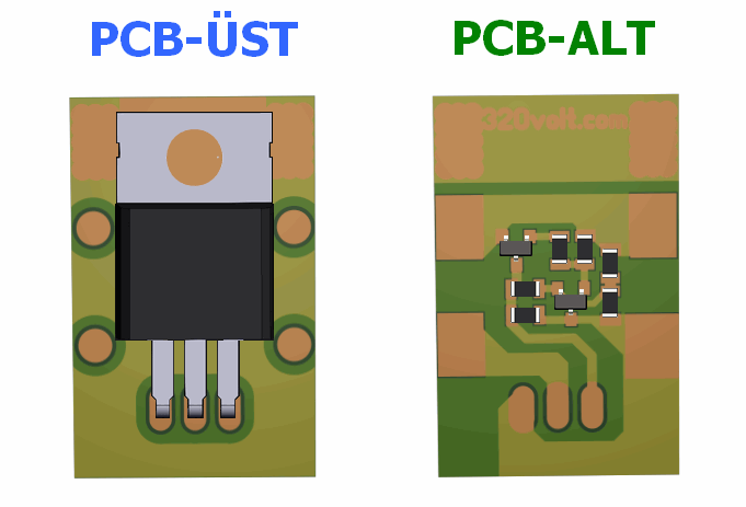
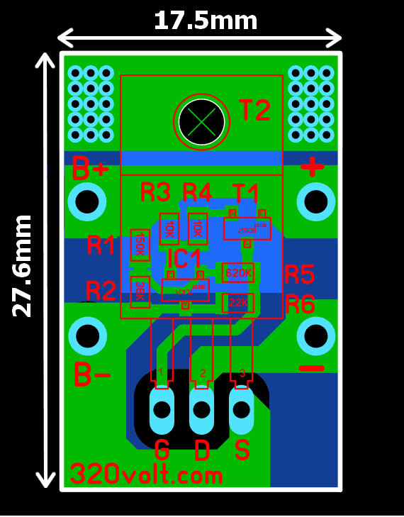
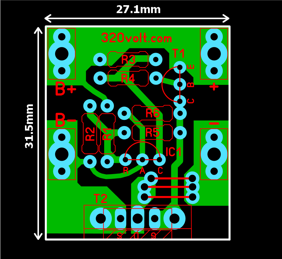
I prepared 2 PCB drawings, one is SMD and the other is DIP case. In the SMD version, part of the upper and lower layers are used for cooling. In the DIP PCB design, a cooler can be installed depending on the load drawn, and the TO247 large case transistor can also be connected.
Battery Protection Circuit Diagram
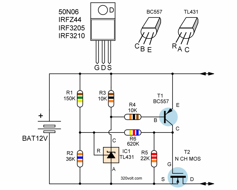


Which resistors are the reference resistors?
r1, r2
Can i take the TLV431 for cut off under 2,0 volts?
Würde mich auch interessieren, bräuchte solch eine Schaltung für mein CAR-System 1:87!
Hallo, leider habe ich das Projekt nicht weiter verfolgt. Ich wollte eine Ladeschaltung für eine Natrium-Chlorid-Akkuzelle bauen.
Mit freundlichen Grüßen
Dirk