Unlike other applications that attempt PIC18F2550 development board “USB bootloader” option for the project for which you want to apply with the PIC18F2550 keep a circuit will provide great convenience for.
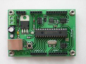
PIC18F2550 Application Board PCB

Hardware; PIC 18f2550 I/SP microcontroller., 24Cxx EEPROM (I2c communication with), 20 MHz crystal., 6-15V power supply input., 5V 1A regulated output., USB support., ICSP programming, Pin header I/O terminal system
General features and usage
1-USB: USB support is the most important feature of self PIC 18f2550 aygün surgical instruments carried out. In this way, you can have a quick communication with your computer via USB.
2-24Cxx EEPROM with I2c serial communication protocol, communicate with each other on the card: an eeprom.
3-ICSP programmer with ICSP support from microdenetleyicinizi over a: removing the card on the program.
4-5V regulated: regulate the IC Card on the 7805 5v supply is provided through microdenetleyicinizin.
5-ICSP-jumpers J1 and J2 I/O with B6 and B7: ports on demand for ICSP programming or I/O port allows you the choice of using.
6-LVP: J3 jumper is inserted ICSP programming with low voltage mode programming. (Supports Low voltage programming for programmers.)
7-I2c – I/O: J4 and J5 jumpers B0 and B1 ports on demand through the I2c communication is the use of the eeprom or I/O port allows you the choice of using.
8-USB-I/O: J6 and J7 thanks to C4 and C5 ports on demand USB communication jumpers or the ability to use selection as I port.
9. Power Led: indicates whether the + 5v supply.
10-Reset: old Microdenetliyicinin foot pulls MCLR pulls back. Reset the reset is activated from the program.
11-Power Out Terminal: terminal 4 output. One of these 2 GND (negative), and others;
+ V is the same as the voltage is entered into clips on the card:.
+ 5V output voltage circuit is: (max. 1A)
12-Port I/O Terminal: terminal system in all ports with active Mikrodenetliyicinin pinheader is available.
PIC18F2550 Board ICSP Connection


On-board supply and the I / O terminals to the top pcb mounting system is designed as a pinhead, according to the template established on their drawings printed circuit boards or perforated plate circuits that can operate easily.


author: Cenk Cemil UNUR [email protected] – Bootloader PIC18F2550 Circuit of the proteus isis, ares files and microchip software:
Dynamo-Powered Bike LED Lights
White LEDs in lighting and more powerful power LEDs are now used in all areas. We shared a lot earlier project led lighting led lights for bikes in the current article, I will discuss the application.
Led the supply of the bike from the alternator getting additional batteries not need to use the picture above you can see the headlights per channel 40 white leds led to the placement of LED flashlight fragmentation led the portion in the separated bike placed.