Hello friends, this article, unipolar stepper motor control circuit related work.
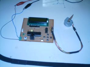
The purpose of this circuit is connected to unpolar stepper motor I designed buttons, select the number of steps we determined the direction, speed, and with it a system that implements the step motor commands. Pic16f877 microcontroller circuit.

When first working circuit stepper motor 120 degree back and forth by applying signal makes zero adjustment. Located on the circuit using the arrow keys to switch between menus and menu you can adjust the volume. The engine speed setting step / sec are denominated in more than 200 steps / sec and at least 1adım/sani of moving at the speed .motor horse could step count up to 200 steps and at least one step atabilir.devre maximum of an engine winding 500 mA current passed. As motor drive uln2803 darlington transistor integrated connection is selected.


Unipolar stepper motor control with PIC16F877 project belongs to proteus simulation file PicBasic Pro code files:


AT90S8535 SG2524 PWM Solar Panel PV inverter Circuit
Solar Energy PV inverter systems used in energy production a detailed study about all the details about the project (in English) is. PV conversion control is provided by Atmel microcontrollers at90s8535 (source software has c) In solid sg2524 PWM (sg3524, uc3524, ka3524) calculations have been used transformer windings information. In addition, all of the layers separate, circuit diagram, pcb diagram of the entire project’s.
About this topic, so a detailed source I could find did not think 🙂 or even an intermediate forum request had been my best I’ve done much good I did not have but detyl a source I find that I will share told the microcontroller, power electronics be helpful to be influenced, to give an example
About this topic, so a detailed source I could find did not think 🙂 or even an intermediate forum request had been my best I’ve done much good I did not have but detyl a source I find that I will share told the microcontroller, power electronics be helpful to be influenced, to give an example