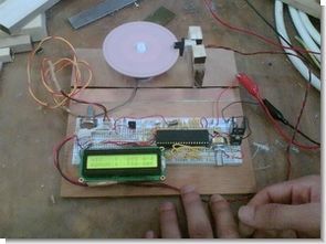
Encoder circuit showing motor speed on LCD with PIC16F877 Microcontroller Explanations about program and circuit The flow chart of the project consists of two parts. These; is the flowchart of the main program and the interrupt routine is the flowchart.
PORTA and PORTB directions are defined in the main program. Then the program enters an infinite loop and a pulse is expected from the encoder. The “count” variable is incremented by one each time a pulse is received from the encoder.
The interrupt routine goes every 66 ms. At the beginning of the program, the LCD is prepared again. Then every 66 ms the speed of the motor is calculated and printed on the peer.
Again, since ADC is used in our program, the speed of the motor is adjusted with PWM. PWM is already mentioned in the flowchart.
PIC16F877 Motors Speed indicator Encoder Schematic


Encoder project Files isis simulation schematic and pic c source code files


TDA8138 Two Channel Multi Regulator Circuit 5V 12V
5v 12v Multi TDA8138 two channel Regulator Circuit diagram and schematic drawing eagle TDA8138 is a monolithic dual positive voltage regulator designed to provide fixed precision output voltages of 5.1V and 12V at currents up to 1A. disable and reset
TDA8138 5V 12V Fix