A detailed project completed with filter and cabinet design, there are pcb cabinet calculations and other drawings for the circuit, an excel calculation table for the amplifier input, shared in the active bass filter circuit with tl072 opamps. The subwoofer cabinet is made of MDF.
Mini Subwoofer This project was started to test the principles of creating an active subwoofer. Preferring to err on a small scale, I decided to build a small version first, using a small 6.5-inch Peerless speaker I once bought on sale (thinking it might work someday).
The subwoofer is housed in a 10.5 l closed cabinet made of heavy MFD plates. The subwoofer uses a small 25 amplifier to power it and a small electronic equalizer that extends the output up to 32 Hz.
This won’t shake the foundation as it’s not a “THX ultra” rated subwoofer, but it’s still suitable for most purposes and no smaller than some commercially available types used for smaller satellite systems.
The circuits and principles shown here can easily be used to create a larger sub-woofer that can provide the bass foundation of your dreams!
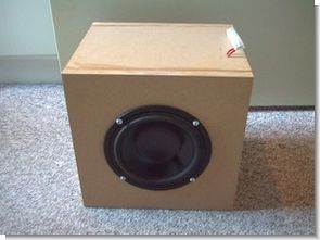
Subwoofer Cabinet Project


Simulation of woofer in a 10.5 l sealed enclosure. There are usable outputs up to about 50 Hz, which isn’t too bad but not good enough to be called a sub-woofer. (simulation with PCLoud4).
Parameters for the system using filler (Rockwool or Acustilux):
Etc. 10.5 liters
f3 55.8Hz
often 66.3 Hz
Qtc 0.88
Peak 0.57db
Bass Equalizers
equalizer #1
The equalizer used here is AES [1]’s J.E Benson and W. Marshall Leach Jr. It was presented by its members and its history goes back to the late 70s. Theoretically, the overall resonant frequency of the system using a closed enclosure and electronic stabilizer can be found as:
Using the numbers found by the simulation program, we get a new fc = 44.5 Hz, which is much better than without the equalizer. The combined system will have a 4th order butterworth system (bass reflex) with 24 db/octave reduction compared to closed systems 12 db/octave reduction.
Of course you can find more suitable speakers for this type of system, but this system was not designed as the main sub for the THX system and a 44.5 Hz fc is actually not bad at all.
There is no magic here, the physical laws still exist and the speaker still needs to move a lot of air to output high at low frequencies. What we get is the possibility of using a smaller enclosure at the expense of using a larger amplifier! Today this isn’t really an issue and you will increasingly see systems like the Sunfire True Sub commercially and systems powered by a class D amplifier from Velodyne that uses a relatively small loudspeaker with extreme shock capability in very small enclosures.
Going back to our system here, we can see that at 45 Hz we get an extra gain of about 3 dB, which really isn’t much and wouldn’t require a huge amplifier, so we can still go for the small 25 W amplifier posted.
The circuit is based on two 2nd order high pass filters and three opamps configured as a modified differential amp.
This project has been started in order to try out the principles of building an active subwoofer. As I would rather make mistakes on a small scale, I decided to build a small version first using a small 6,5 inch Peerless speaker I once bought on a sale (thinking it would come in handy one day).
The subwoofer is housed in a 10,5 l sealed cabinet of heavy MFD plates. The subwoofer uses the small 25 amplifier to power it, and a small electronic equaliser which extends the output down to 32 Hz.
Source : sensibleaudio.dk/mini-sub/mini-sub.htm Subwoofer Cabinet and Active Filter Circuit schematic pcb files alternative link:


PIC16F877 LCD Motors Speed indicator Encoder Circuit
PIC16F877 microcontroller with LCD also shows the engine speed encoder circuit. These and the interrupt routine of the main program flow chart is a flow chart.
PORT in the main program and is defined PORTB aspects. Then the program enters an infinite loop and is expected to come from the encoder pulse. Each pulse from the encoder when the “count” variable is incremented by one.
An interrupt routine to get every 66 ms. LCD is prepared to start the program again. Then every 66 ms to a motor speed is calculated and printed peers. Again using our program the ADC is adjusted by the motor speed PWM. PWM is already indicated in the flow chart.
Could you please apload the PCB again. The File cannot be accessed. Thanks in advance .
Hello, I checked, the file can be accessed.
Okay I will try downloading again . Thank you for responding
Please post the PCB again. Thank you in advance