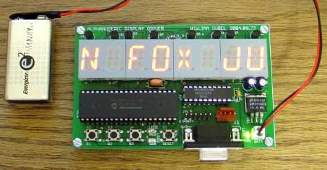
Pic16f874p alphanumeric LED display driver circuit board with microcontroller builds on the applied bred led display 74HC238, 74HC238 is driven by com also has a connection with max233 pcb printed circuit drawing in addition to the (eagle) there. PIC Software HiTech PICC compiler written in VHDL source code are in addition PALCE16V8. Sisis supply LM2940 regulator in there. Circuit with 9v battery can run.
PICmicro Alphanumeric Display Driver

Alphanumeric Display Driver is driven by a PIC microcontroller programmed to interface 15-segment LED displays. This is a 5MB video of the screen scrolling through a message. I bought some LED displays at Digikey for fun but soon realized I would need a driver chip to use them. Maxim offers a lot of nice drivers for matrix displays and 7-segment displays, but if you need a custom driver for a random display (like the 15-segment displays I bought), you may need to design your own. It’s not difficult and here you can find some code to work with PIC series microcontrollers using interrupts.
Completed display module using PIC based display driver. The message ‘FAST BROWN FOX JUMPED OVER LAZY DOG’ is displayed on the screen.
Before I did the design on the PCB, I put it together on a breadboard to make sure it was bright enough. Because the displays are multiplexed, I need to supply enough current to each digit (12% of the time they’re on) for them to appear bright enough on average. I found that the displays are only readable using transistors for the common cathodes of the displays, which saves 15 transistors.

DigiKey part numbers for the 15 segment displays I use are 160-1012-ND for green characters and 160-1010-ND for red/orange. You can download the data sheet in pdf format here.
In the picture above, the screen scrolls to “*** FAST BROWN FOX JUMPS OVER THE LAZY DOG 1234567890 TIMES” to test all the characters. I’m using the PIC16F77 by Microchip because it has so many output pins (perfect for an LED driver). You can also use a PIC16F877A because it has all the features you want and is supported by the free HiTech PICC compiler. Image processing takes up very little of the current processing of microcontrollers and runs from the interrupt routine so it is transparent to the programmer. Below is a sketch of what I imagine the characters should look like:
The digits are multiplexed and refreshed at approximately 75 Hz. I have placed a MAX202 level shifter on the breadboard as it will allow to update the message with RS232 but I haven’t done that in the code yet. The other support chip is 3 to 8 active high decoders with the same function as the 74’238. The active low version (74’138) is easy to find, but the active high is not, so I coded one in VHDL for a PALCE16V8.
“Why bother with a separate decoder chip when there are so many outputs?” you may ask. Well, it saves valuable microcontroller outputs for other things and lets you duplicate many displays. Increasing the number of displays to 16 requires only one additional output line from the microcontroller. You will still need a larger PAL (or CPLD).
As for the circuit, it should be pretty obvious that I’ve reproduced the figures from the enlarged picture to the microcontroller. If not, check out some sites on the internet to see how it’s done. The 8 transistors are 2N3904 but you can use any NPN transistor to switch ground to screens. If you try to connect the ground directly to a microcontroller or (active low) 74’138 you will find that your screens are very dim.
This is because these outputs can only drop to a maximum of 25 to 50 mA, leaving you only about 3 mA per segment. Divide that by 8 (since each is only 1/8 of the time) and you can see why they are dim. The transistors can easily switch between 100 and 200 mA so the brightness is acceptable. Ideally (it won’t be here), you want a peak current of about 40 mA per segment as they only make up a fraction of the total time. Some screens are common anode and you will use 2N3906 PNP transistors to VCC instead. By the way, this works at 5 volts but can also run at lower voltages depending on the clock you use.
Source: goo.gl/0GjtD Alphanumeric Display Drivers hi tech c source code schematic pcb alternative link:


Large 7-Segment Display Circuit ULN2803 PIC16F876A
Large size also display the prices are expensive, but they also have a limit if you make yourself big size LED display can achieve. Led diplay pic16f876 used in the control circuit of the LEDs are driven by uln2803 software ccs c prepared by the working frequency of 20MHz.