PIC16F648A LC meter Simply, + -1% accuracy battery powered compact LC for low power consumption does not have a meter is recommended. C measurement range is 0.1pF ~ 1uF (renewal auto range) L range is measured 0.01uH ~ 100mH (renewal auto range) L saw the experiment in measuring 1cm in line (0.01 uH) displays. LC meter circuit 16f648 microcontroller prepared with 2 × 16 LCD display displays the measurement value on
Simply, + -1% accuracy battery powered compact LC for low power consumption does not have a meter is recommended. C measurement range is 0.1pF ~ 1uF (renewal auto range) L range is measured 0.01uH ~ 100mH (renewal auto range) L saw the experiment in measuring 1cm in line (0.01 uH) displays.
To adjust the relay is simply a move seconds. 600kHz oscillation about the CL is not measured by calculating the change in frequency as the LC and values. f = 1 / (2π √ LC) To this calculation FP.TXT above uses. (Floating point) Add a relay 1000P is a great software as required accuracy of the capacitor. (More as it comes)
2N7000 MOS FET relays instead of the hand is not able to use TR saw the making, accuracy is to move anyway. 5V is the original, 4V moves. AA has to make.
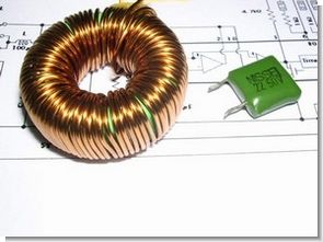
PIC16F648A LCD LC meter


LCD LC meter schematic pic assembly and hex code files:


Voltage Current Regulated 2N3055 LM723 Power Supply
LM723 a basic circuit configuration is written in the Specification Sheet, LM723 stability is considerably higher for the load, 17V 3A load voltage drop of 3 ~ 4mV was about.
This circuit has stabilized following changes to the configuration of the circuit. Side of the circuit (the thick part of the circuit diagram) – the (part of the circuit diagram of a thin line) is part of, 0.2mm thick copper plate × 6mm wide uses LM723 circuits by changing the voltage of the previous range of 0 (about 60mV actual) ~ 21.5V from, 2.6 ~ 25V now. load is less than 23V 4A to ripple around without