Ps2 keyboard emulator with a computer circuit PIC16F84 PIC16F84 micro-controller for use with the PS2 keyboard assembly prepared with a sample project pic software. circuit given the necessary information materials list and code expansions keyboard input and output data connection and it’s a lot more information
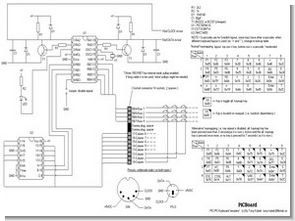
Keyboard Emulator Schematic

PC-Keyboard emulator using a PIC16F84
Scan a 32 key keyboard ( with alternative mapping = 64 keys )
A set of routines which forms a PC keyboard emulator. Routines included are: Interrupt controlled clock ( used for kb comm. and ‘heart beat ) A 4×8 matrix keyboard scanner ( using an 74HCT4051 3 to 8 analogue multiplexer ) Communincation with PC keyboard controller, both send end recive.
PC keyboard routines are using 4 pins (2 inputs & 2 outputs) to control keyboard’s 2 bidirectional OC lines (CLK & DATA). The following ‘drawing’ conceptually shows how to connect the related pins/lines ( ASCII art/info shamelessly ‘borrowed’ from http://www.arne.si/~mauricio/PIC.HTM )
An identical circuit is used for the DATA line. Note: The 2N2222 transitors can be replaced with BC337 ( NPN ) which are cheaper The keyboard matrix routines are using RB4-RB7 as inputs. and RB0-RB2 as output to/from an 3 to 8 multiplexer so that it can read up to 4×8 keys ( 32 ).
RA4/TOCK1 is an input from an jumper, if low then keyrepeat is disabled and alt-key is enabled instead i.e. instead of repeating a key that has been depressed a certain amount of time, a bit is set that can change the scancode for a key ( of course, all keys can have an alternate scancode ).
To exit the alt. keymap press the ‘enter alt. keymap’ key once again or wait until timeout. ( defined in the code ) NOTE !! The so called ‘enter alt. keymap’ key is hardcoded, i.e the key i’ve choosen in this ‘example’ is Column 1 Row 2, if this is to be changed code has to be changed/moved in the debounce and checkkeystate routines. ( marked with <——-Alt keymap code——-> )
RB3 is currently used for a flashing diode. ( running ) Note my real keyboard ( KeyTronic ) uses a clock rate of 40 us, my implementation uses about 50 us, easily to change.
Basic program structure
Init – Initialise ports , ram, int, vars Start delay – After init the timer int is enabled and the flashing led will start to toggle ( flash ). Before I enter the mainloop ( and send any keycodes ) I wait until the led has flashed twice. This is of course not really needed but I normally like to have some kind of start delay ( I know 1 sec is a bit much 🙂 )
Time Int – The timer interrupt (BIG), runs in the background: – ‘Normal’ rate 0.5 ms, when in rx/tx rate is 27 us – Performs an rx/tx check, then jumps to rx, tx or ‘heart beat’ code. – TX code sends a byte to pc, at a rate of 27us per int.
The int rate is actually double the bit rate, as a bit is shifted out in the middle of the clock pulse, I’ve seen different implementations of this and I think
that the bit is not sampled until clock goes low again BUT when logging my keyboard ( Keytronic ) this is the way that it does it. When all bits are sent, stopbit/parity is sent.
And the key is removed from the buffer. After stopbit/parity is sent, a delay is inserted ( 0.5 ms ) before next rx/tx check. – RX code recevies a byte from the pc, PIC is controlling clock !! Int rate ( 27 us ) is, again, double bit rate. Toggles clock and samples the data pin to read a byte from pc. When reception is finished an ‘handshake’ takes place.
When a byte has been recevied a routine is called to check which command and/or data was received. If it was keyboard rate/delay or led status byte, it is stored in local ram variables. NOTE: The rate/delay is not actually used for key repeat as the code is right now ( I use my ‘own’ fixed rate/delay ) however it is very easy to implement.
After handshake a delay is inserted ( 0.5 ms ) before next rx/tx check. – ‘Heart beat’ ( idle code 0.5 ms tick ) performs: – Check clock/data lines to see if pc wants to send something or if tx is allowed.
– If tx is possible it checks the keybuffer for an available key and if keys are in buffer then it initiates a tx seq. and sets the int rate to 27 us.
– If the pc wants to send something, an rx seq. is initiated ( there is some handshaking involved, during which the int rate is set to 60 us ) after that, the int rate is set to 27 us and an rx seq is started.
– Divides some clock counters to achive 10ms,100ms,500ms sections.
– In 100 ms section it performes a numlock status check and keyrepeat check ( both rate and delay is local in 100 ms ticks, thats why I dont use the ‘real’ rate delay )
– If numlock status is not the desired one code is called to toggle the numlock status.
– If a key has been pressed long enough for repeat, an bit is set so we can repeat the key ( send the scancode again ) in the main loop.
– In 500 ms section the led is toggled on each loop
– Some various alternative keymap checks to get out of alternative keymap. ( i’ll get to that in a bit )
Main loop – Outputs an adress to the 4051 multiplexer waits 1 ms reads the row inputs ( 4 bits/keys ), increments address and outputs the new adress, waits 1 ms and reads the input ( next 4 bits/keys ). Now using the address counter, calls a debounce/send routine that first debounces the input, ( four consecutive readings before current state is affected ) and when a key is changed a make/break code is sent ( put in buffer ).
In the next loop the next two columns are read etc. until all 4 column pairs are read.
– If keyrepeat is enabled ( see pin conf. above ) the repeat flag is checked and if ‘1’ the last pressed key scancode is sent again ( put in buffer ).
– If keyrepeat is not enabled( alternative keymap is enabled instead ) then various checks to exit the alternative keymap are performed instead.
Scancodes for all key are located in a lookup table at the end of this file, each key has four program rows, to make room for extended codes and alt. keymap codes.
Explanation of ‘alternative’ keymap:
Using this program ( or an heavily modified version of it anyway 🙂 ) on a computer running Windows posed some small problems namely: -The keyboard ( mapping ) I used did not have any ‘special’ key such as ,, etc.
-In windows, things can go wrong, 🙂 if a dialog pops up or something similar there were just no way one could dispose of this with the keymapping i used.
– ‘Only’ 28 keys were implemented ( hardware wise ).
In this particular case the keyrepeat was disabled ( due to the nature of the application ) Therefore i came up with the solution to use the keyrepeat related routines and vars.
To handle a so called ‘alternative’ keymapping. This means that an key is dedicated to be the alt. keymap toggle key, when pressing this longer than the programmed repeat delay, instead of repeating the key a bit variable is set to use another set of scancodes for the keyboard. This ‘alternative’ keymap is then enabled even though the alt. keymap toggle key is released, but it also incorporates an timeout that will return to normal keymap if no key is pressed within a certain time ( currently 7 sec )
Of course pressing the alt. keymap toggle key again ( while in alt. keymap ) will return the keyboard to the normal keymap. NOTE !! the key choosen for the alt. keymap toggle is hardcoded, so if the scancode for this is changed in the lookup table, changes have to be made in other routines as well. ( namly : CHECK_KEY_STATE, and DEBOUNCE_COLUMN routines ) While in alt. keymap each key CAN have an alternative scancode ( see lookup table ). Also by using the numlock bit, one can toggle numlock status ‘on the fly’ when entering or exiting the alt keymap.
Some notes about the local keyboard interface ( matrix ): Although the hardware circuit and software allows virtually unlimited simultaneosly pressed keys, the keyboard matrix itself normally poses some limitations on this. If an keymatrix without any protective diodes are used then one would have loops INSIDE the keymatrix itself when multiple keys are pressed in different columns .
Look at the ( although horrible -) ) ASCII art below(internal weak pullup enabled):
0 – Key is free
1 – Key is pressed ( connection between hor/ver rows )
Three keys pressed adressing ( reading ) left column :
This works as intended, we can read a ‘0’ on pic inputs 2,3 which is what we expected. The current ( signal ) follows the route marked with ‘*’: ( only the ‘signal path’ is shown for clarity )
However, when we now read ( address ) the right column instead we do not read what is expected ( same three keys still pressed )
As you can see the ‘signal’ travels in the keymatrix itself ( where the ‘<-‘ is )and will cause a ‘ghost’ signal to be read on the pic. So instead
of having an ‘0’ on input 2 only we also can read an ‘0’ on input 3. This is because the two keys in column 1 are interconnected ( when they are pressed ). Keep this in mind if you are planning to support multiple pressed keys.
Some suggestions for ‘improvements’ or alternations
– Using the jumper ‘disable-repeat’ as a dedicated key for switching to alternative keymapping.
– Enable repeat in alternative keymapping
– Clean up TX/RX code ( a bit messy )
– Using the led output ( or jumper input ) as an extra adress line to the multiplexers ( in this case 2 pcs. 74HCT4051 ) we could have 4×16 keys instead. Would require some heavy modifications though as there are not much ram/program space left. But if alternative keymapping is discarded ( most likely if one has 64 keys ) each key in the lookup table only needs to be 2 lines instead of 4. That would ‘only’ require some modifications to preserv ram.
– Using the EERAM for ‘macros’ or similar ( not used at all now )
LEDGEND
I tend to use the following when naming vars. etc. :
( yes i DO like long names )
For ‘general’ purpose pins:
An input pin is named I_xxx_Name where :
I_ – This is an input pin -)
xxx_ – Optional what type of input, jmp=jumper etc.
Name – Self explanatory
An output pin is named O_xxx_Name where:
O_ – This is an output pin -)
xxx_ – Optional what type of output, led=LED etc.
Name – Self explanatory
Application(function) specific pins:
An application(function) specific pin is named xxName where:
xx – What/Where, for example pc=To/From pc
Name – Self explanatory ( what does it control etc )
An #define/constant/equ (no pin or ram ) uses all capital letters e.x. #define BREAK 0xF0
A bit variable will always start with ‘_’. For example ‘_IsLedStatus’
All other ( mostly ramvars. ) are named in various ways.
Keyboard Emulator PIC ASM files


LED Display with PIC16F84 Adjustable Timer Circuit
16f84 cd4511 decoder integrated circuit and timing controller based on the 7 segment LED display with display and buzzer sound can give warning adjustment is done with the buttons numbered 1,2,3 MPASM assembler source. Asm software available
Darkroom timer circuit schematic