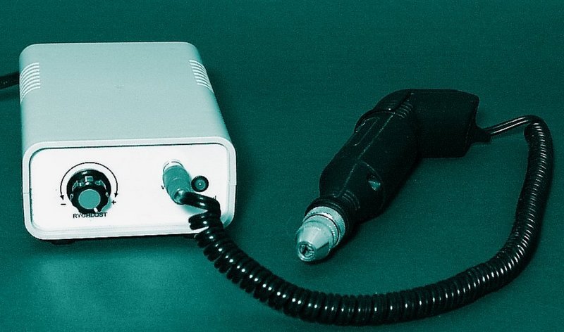
The circuit is designed for DC 12V motor and has been tested with miniature drill BOSCH MBM04. Because they can take motor from the source of higher currents, it is appropriate their drive speed pulse while maintaining maximum Tension. Unlike speed control by changing the voltage it has a pulse-width application modulation advantage lower power loss on the regulator end element while maintaining engine torque. Ours the device operates at about 30 kHz.
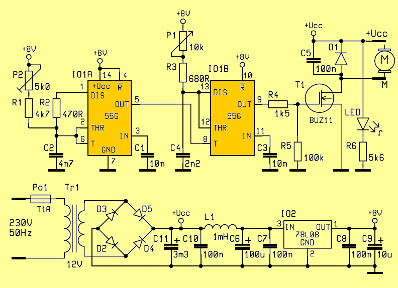
The primary side of the transformer is protected fuse PO1. From the exit the transformer, the AC voltage is rectified diode bridge D2 to D5 and beyond the DC voltage is filtered by the capacitors C10 and C11. Other filtering the elements in the power circuit are L1 coil and C6 and C7 capacitors to prevent intrusion of high frequency pulses into the IO2 stabilizer input. From the exit the IO2 stabilizer type 78L08 is powered double timer IO1 type NE556.
Schematic Diagram Speed controller Circuit
After the PCB is installed, check it the side of the connections, whether tin bridges between links especially in the area of power supply. Distances between power supply wires it must be at least 5 mm. Potentiometer P1 dial to the left, trimmer P2 to the right. Connect DC to the output 12 V motor (polarity required, the direction of rotation) and connect AC supply voltage 230V / 50Hz.
ATTENTION! We are now working carefully for compliance all safety regulations! Turn potentiometer P1 slowly up to the rightmost position, and must the engine speed increases. Then turn the P2 trimmer slowly to the left (potentiometer P1 must be in the rightmost position) until it reaches a marked position the speed of the motorcycle. Then with trimmer, turn to the right until the maximum speed is restored and leave the trimmer in this position. It is appropriate trim the trimmer with varnish (eg varnish nails) to ensure its position. In this way, we made the settings frequency in conjunction with the output length pulse of a monostable circuit. Finally, unplug the power supply.
R1 4k7
R2 470R
R3 680R
R4 1k5
R5 100k
R6 5k6
P1 10k
P2 5k
C1, C3 10n
C2 4n7 CF2
C4 2k2 CF2
C5, C7, C8, C10 100n
C6 100μ/35V
C9 10μ/35V
C11 3m3/25V
D1 1N4007
D2 – D5 BY550
L1 TL.1000μH
T1 BUZ11
IO1 NE556
IO2 78L08
PO1 165.000 1A
TR1 12V 60W AC
1× LED 5mm
FILE DOWNLOAD LINK LIST (in TXT format): LINKS-26129.zip


Amplifier 2.1 with TDA7377
Amplifier 2.1 with TDA7377
Small amplifier TDA7377 of 15W + 15W + 30W in 4 ohms At the request of our followers, we have developed an amplifier with the following characteristics: The TDA7377 is the main component. It has 4 outputs that can deliver a power of 15W each. we distribute them as follows: First, we have 2 outputs of 15W, which form a stereo amplifier. On the other hand there is another mono amplifier, which is formed by the other 2 outputs in bridge mode, and delivers a power of 30W.
Another additional circuit is a low pass filter that is connected to the input of the 30W mono amplifier. So this one only delivers low frequencies. While the stereo outputs, have a frequency response approximately, from 100Hz, to 20,000 Htz.
Another interesting feature of our design is that it is fed with a simple font. In addition, the preamplifier, the low pass filter, the rectifier source and the amplifiers are all on the same card.
TDA7377 Amplifier and TL081 Bass Filter Schematic
NE556 Régulateur de vitesse Circuit Moteurs CC
Le circuit est conçu pour un moteur DC 12V et a été testé avec une perceuse miniature BOSCH MBM04. Parce qu’ils peuvent prendre le moteur de la source de courants plus élevés, il convient de leur impulsion de vitesse d’entraînement tout en maintenant une tension maximale. Contrairement au contrôle de la vitesse en modifiant la tension, il présente un avantage de modulation de la largeur d’impulsion qui réduit la perte de puissance sur l’élément d’extrémité du régulateur tout en maintenant le couple moteur. Notre appareil fonctionne à environ 30 kHz.
Le côté primaire du transformateur est protégé par le fusible PO1. A la sortie du transformateur, la tension alternative est redressée en pont de diode D2 à D5 et au-delà de la tension continue est filtrée par les condensateurs C10 et C11. Les autres éléments filtrant les éléments du circuit de puissance sont la bobine L1 et les condensateurs C6 et C7 pour empêcher l’intrusion d’impulsions haute fréquence dans l’entrée du stabilisateur IO2. Depuis la sortie, le stabilisateur IO2 type 78L08 est alimenté par un double temporisateur IO1 type NE556.
Schéma du circuit du contrôleur de vitesse