LED brightness control gives you tremendous control over the light emitted by the LEDs. However, to use them in a safe manner for LEDs and other devices or electrical installations, use appropriate regulators and power supplies.
Inputs of unused gates are attached to the power supply. The P1 10 kohm potentiometer allows the PWM to vary within a very wide range from about 2% to 99%. The pulse waveform given to the gate of the T1 IRF7201 transistor opens and closes it cyclically and the average power delivered to the receiver connected to the OUT connector is dependent on the waveform fill factor of the generator. In this way, the PR1 potentiometer enables smooth control of the power supplied to the receiver. Thanks to impulse work, the losses in the T1 IRF7201 transistor are small and do not require an additional heatsink.
LED Dimmer schematic diagram
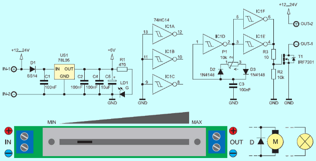
a reliable light regulator that is switched between the power source and the LED strip. By analyzing the operation, the U1D inverter works in a single-gate rectangular waveform generator. The frequency of its operation is determined by the capacitance C3, and the resistance of the potentiometer P1. Paralleled U1E gates, U1F control MOSFET IRF7201 T1 transistor.
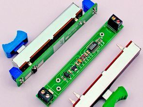
The basic task of the controller is to adjust the brightness of the tapes and the LED modules. With the slider potentiometer, the width of the module is not much larger than the popular LED strips and is only 14 mm long and 95 mm long. The regulator can also be used for dimming of 12 V and speed control of DC motors. The dimmer module presently works well at 24 volts.
In conjunction with an inductive load, in practice with DC motors it is necessary to connect in parallel to the output of the “fast” semiconductor diode, eg Schottky. Without the diode D on the T1 transistor drain at the time of switching it off, positive pulses would appear with a voltage much higher than the supply voltage. They would have an amplitude of several dozen volts, which could damage the transistor. When controlling the brightness of “normal” light bulbs, there is no need to attach any external components. The indicator of the power supply is LD1 LED. The dimmer module shown works properly with a load of up to 75 W.
![]()
FILE DOWNLOAD LINK LIST (in TXT format): LINKS-25878.zip


Mosfet LED-Abblendschalter 12V-24V
Die LED-Helligkeitssteuerung gibt Ihnen eine enorme Kontrolle über das von den LEDs ausgestrahlte Licht. Verwenden Sie jedoch geeignete Regler und Netzteile, um sie sicher für LEDs und andere Geräte oder elektrische Installationen zu verwenden.
Eingänge von nicht verwendeten Gates sind an die Stromversorgung angeschlossen. Mit dem Potentiometer P1 10 kohm kann der PWM in einem sehr großen Bereich von etwa 2% bis 99% variieren. Die Pulswellenform, die dem Gate des T1 IRF7201-Transistors gegeben wird, öffnet und schließt sie zyklisch und die durchschnittliche Leistung, die an den Empfänger geliefert wird, der mit dem OUT-Anschluss verbunden ist, hängt von dem Wellenformfüllfaktor des Generators ab. Auf diese Weise ermöglicht das Potentiometer PR1 eine sanfte Kontrolle der Stromversorgung des Empfängers. Dank der Impulsarbeit sind die Verluste im Transistor T1 IRF7201 gering und benötigen keinen zusätzlichen Kühlkörper.
LED-Dimmer schematische Darstellung