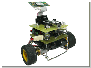
This design is a continuation of the already released Robot 1.1 design. The aim of the new design was overall smaller dimensions, easier usability of components and the possibility to use Spezial Electronic’s connectBlue Bluetooth module for remote control of the robot. The robot can therefore autonomously avoid obstacles or be controlled wirelessly via Bluetooth.
The electronic part is divided into a master and a secondary board. The motherboard provides engine start and obstacle detection. The side panel is mainly used to connect the Bluetooth module, and the robot is fully functional without it, but cannot be controlled wirelessly. The mechanical construction is very simple, thanks to the use of the largest number of parts available.
The body of the robot is made of copper wires, four AAA Ni-MH cells are used as the power source, and the wheels are attached directly to the transmission shaft, which is part of the motorcycle. Control programs programmed in Visual Studio are used for wireless control of the robot via Bluetooth for both Windows operating system and Windows Mobile.
The voltage from the battery is connected to terminal block X1 and LED5 indicates its presence. Given that stabilization and possibly further adjustments to the supply voltage will only require the manufacture of a larger PCB and the battery voltage will range from about 4.5V to 5.5V, no further adjustments to the supply voltage have been made and just a capacitor S1 switch connected C1.
As can be seen from the diagram, LED5 indicates the presence of the supply voltage. It was also necessary to obtain a supply voltage of about 3.6V for the microcontroller IC1. The required voltage was obtained by connecting the 1N4148 diodes (D1 and D2) in series, decreasing by 1.4 V, i.e. from 5 V to the required 3.6 V. Due to interference from the motors, the L1 and L2 coils had to be included in the power path of the receiver and main processor, which sufficiently eliminated unwanted interference.
The most important component of the motherboard, and therefore of the entire robot, is the Freescale MC9S08QG8 microcontroller in the PDIP16 package (IC1). For example, it has 8,000 bytes of flash memory for the program, 512 bytes of RAM, a 16-bit timer, an 8-bit timer, and a UART, SPI, and I2C communication interface. Optimized for programs translated from C language to machine code, the HCS08 core can be clocked up to a frequency of 20 MHz from an external source.
However, PidiBot uses the maximum frequency of the adjustable internal clock source which is 8.3712 MHz. It is necessary to load a program into the Flash memory of the microcontroller using the BDM interface, which can be downloaded from here. This program provides engine starting using a dual MOSFET transistor IRF7303 (T1) integrated in an SO8 package. The transistors are capable of switching a current of up to 3.5 A, which is more than enough considering the motors used.
An SFH5110-36 IR pulse receiver and demodulator (IC2) was used for obstacle detection. The latter is connected to the microcontroller through the resistor R8, because the voltage of the output signals is higher than the supply voltage of the microcontroller and therefore can be damaged. The receiver itself tries to catch the rays reflected from the obstacle and informs the microcontroller about them.
The rays are emitted alternately by a pair of IR LEDs (LED1 and LED2). The intensity at which the infrared LEDs will pulse is adjusted using the R1 and R3 correctors. If an obstacle is detected, LED3 or LED4 will illuminate. Finally, it was necessary to place a connector on the motherboard for the BDM interface, which was used for programming and debugging the microcontroller program.
The most important part of the secondary board is the Freescale MC9S08QG8 microcontroller in the PDIP16 package (IC1), which contains the same program as the main board microcontroller. As mentioned earlier in the short introduction, the side board is mainly used to connect the Bluetooth module to the microcontroller via the SV1 connector.
The cheapest variant was used for PidiBot, the OEMSPA310. It is necessary to solder a straight 9-core cable (or 8-core, since the connection does not use the Reset pin) to the Bluetooth module itself and equip it with a self-cutting connector. The leads are soldered to the connector that the module manufacturer refers to as J6 in the datasheet.
Bluetooth-Controlled Robot Project
The most important component main boards and thus the whole robot is MC9S08QG8 Freescale microcontroller in the case PDIP16 (IC1). UART, SPI a I2C. He has, for example, 8k bytes of flash memory for the program, 512 bytes of RAM, a 16-bit timer, one 8bit timer and communication interface UART, SPI and I2C. His HCS08 core optimized for programs translated into the source code from the C language may be due from an external source and frequency of 20MHz. maximum frequency adjustable internal resources stepping, which employed 8.3712 MHz.


The most important cables for communication with the module are RxD and TxD, which are used for data transfer. The green LED/Switch 1 terminal was connected to the microcontroller only to test the functionality of the AT mode, in which it is possible to set various parameters of the Bluetooth module. According to the datasheet, it is not necessary to connect the Reset pin. Connecting the CTS input pin was also necessary since the Bluetooth module was factory set so that the data flow was controlled by hardware (using CTS and RTS). It is possible to turn off hardware control of the data flow in the AT mode of the Bluetooth module, but in terms of revival it was easier to ground the CTS, so the module constantly sends data to the microcontroller.
One pin of the microcontroller IC1 was used for another IR LED (LED2), which slightly improved the obstacle detection capability. Another terminal was used for the white LEDs (LED1 and LED4). The output used to switch transistor T1 that supplies current to the white LED is also shared by switch S1 which is used to manually turn on the LED. Turning the white LEDs on with a button is done in such a way that the microcontroller turns the LED off for an undetectable moment every 100ms, changing the perception of the pin to the input, testing for a rising edge on the input. button was pressed) and is turned off or on depending on the previous state of the LEDs.
The main task of the microcontroller is to seek and avoid obstacles. The algorithm is very simple and uses the fact that the SFH5110 receiver logs its output while capturing a 36 kHz frequency pulse with a 1:1 variation in our case. 1. And so the microcontroller using the first timer sends 8ms pulse to the left IR LED, nothing is sent for 8ms, 8ms sends a pulse to the right IR LED, nothing is sent for 8ms, the IR LED on the side board lights for 8ms and finally nothing is sent for 8ms. In this way, while the microcontroller sends continuous pulses, it checks the status of the SFH5110 sensor in the loop of the main program. If the receiver signal is captured, the corresponding indicator LED lights (no signal received from the IR LED on the side panel).
The second timer is used to evaluate the data obtained from the sensors and accordingly shuts down the respective motor just in time to avoid hitting an obstacle. Unfortunately, due to size and simplicity requirements, it was not possible to install an H-bridge on the PCB that could change the direction of rotation of the motor, and therefore the robot cannot reverse. This is somewhat offset by adding another IR LED to the side board, improving detection capability.
Another part of the program provides communication with the Bluetooth module. The microcontroller turns the motors and reflectors on or off according to the character it receives. If there is any change (starting the engine, detecting an obstacle) the microcontroller sends a signal so that it is possible to remotely control what is going on with the robot. The list of characters used when communicating with the robot can be seen in the attached source code of the control program for Windows.
Wireless control program:
The PC driver has only been tested under Windows XP, but should also work on the latest Windows Vista. The user interface is very simple. It includes a box to select the serial COM port created after pairing the Bluetooth module with the computer, a button to connect or disconnect, a button to select Manual or Autonomous mode, and buttons to control the robot. However, the robot can also be controlled using the keyboard. Use the I, J, K and L keys to control the robot and use the A key to turn the white LED on or off. The states of the motor and sensors are indicated by LEDs.
The control program was also written for the Windows Mobile operating system. But this version has no buttons, so the robot has to be controlled using the buttons on the keyboard. Buttons *, #, 0 and 8 control the robot, button 1 turns off the white LEDs and button 2 turns them back on. The program should work with most devices with a Bluetooth module and at least Windows Mobile OS version 2.
Source: mica.ic.cz MC9S08QG8 with a Bluetooth-Controlled Robot schematic source code alternative link


PIC16F84 2.7GHz Frequency Meter Circuit 100kHz resolution Picbasic Pro
Frequency meter PIC16F84 with prescaler This small unpretentious frequency is for SHF measures up to 2.7 GHz for which we do not look great precision (eg ATV). Like many circuits of this kind, it is based on the AN592 Application note Microchip.
This is actually a frequency that can operate up to 13 MHz which I added a prescaler LMX5080 by 256. This circuit is no longer manufactured, but it can be replaced by any available prescaler (the value of prescaler is selectable by software).