MAX1811 USB port on to recharge the battery produced an integrated very little material circuit can be established circuit charge status LEDs can be observed also 4.1 volts, 4.2 volts elections and 100mA 500mA charging current can be selected fed lipo li-ion battery charging circuit circuit eagle crafted with PCBs and schema files available
MAX1811 USB Powered Battery Charger


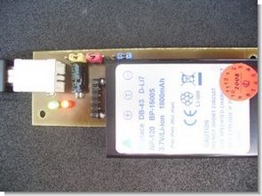
The MAX1811 is a single-cell lithium-ion (Li+) battery charger that can be powered directly from a USB port* or from an external supply up to 6.5V. It has a 0.5% overall battery regulation voltage accuracy to allow maximum utilization of the battery capacity. charger uses an internal FET to deliver up to 500mA charging current to the battery. The device can be configured for either a 4.1V or 4.2V battery, using the SELV input. The SELI input sets the charge current to either 100mA or 500mA. An open-drain output (CHG) indicates charge status. MAX1811 has preconditioning that soft-starts a near-dead battery cell before charging. Other safety features include continuous monitoring of voltage and current and initial checking for fault conditions before charging.
- Charges Single-Cell Li+ Batteries Directly from USB Port
- 0.5% Overall Charging Accuracy
- Minimal External Components
- Input Diode Not Required
- Automatic IC Thermal Regulation
- Preconditions Near-Depleted Cells
- Convenient Power SO-8 Package (1.4W)
- Protected by U.S. Patent # 6,507,172
source grautier.com/ Li-ion Lipo Battery Charger Circuit MAX1811 USB Powered schematic pcb files alternative link:


With Button Control CCS C Circuit LCD display PIC16F877
CCS-C code that prepare “@ fxdev” a project done on request circuit up and down the third button 2 buttons to control the direction of the desired output number appears on the LCD screen when the output of the first (+5 v) ensures that the
LCDs used 2 × 16 pic 2 LEDs on the bar connected to the outputs of simulation by making the necessary changes that will control transistor relay can add elements by