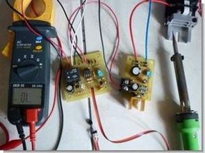
The famous LM35 temperature sensor was used for temperature detection in the circuit, and plenty of microcontroller-controlled circuits were shared with this sensor.
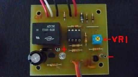
The circuit works with 12 volts DC. Sensitivity can be adjusted between 0-150 ℃ with the VR 1 trimpot control IC LM358 binary op amp circuit output relay with high power devices can be controlled very sensitive simple cheap automatic thermostat
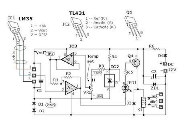
This simple and highly accurate temperature control circuit can be used in automatic temperature control applications. The circuit is based on the temperature sensor LM35, which detects that the micro-Relay will turn on or off when the temperature is higher than the preset temperature.
The electrical device is turned off and the relay is energized when the temperature is lower than the preset temperature. LM35 output voltage 550mV (-55 ℃ ) 1500mV (150
°C). It uses a high precision voltage reference TL431 and a correct comparator LM358 to generate
The preset VR1 and resistor R3 form a variable voltage divider to set the reference voltage. Voltage form from 0V ~ 1.62V. The reference voltage of the buffer of this operational amplifier (A2 in the schematic) is to avoid loading the voltage divider network of VR1 and R3.
For example: to set to 70°C, its circuit is used to keep the temperature of the water container at 70°C. calibration:
1 Get an accurate digital voltmeter and connect TP1 (+) to GND (ground).
2 Slowly set VR1 to desired value (in this example voltage will be around 700 mV

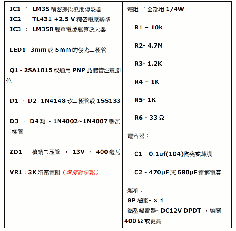
IC1 : LM35
IC2 : TL431
IC3 : LM358
LED1: 5mm
Q1 – 2SA1015 PNP
D1 , D2- 1N4148
D3 , D4 – 1N4002 or 1N4007
ZD1: 13V
VR1:3K
R1 – 10k
R2- 4.7M
R3- 1.2K
R4 – 1K
R5- 1K
R6 – 33 Ω
C1 – 100nf
C2 – 470μF


PICmicro LED tachometer Circuit
Handmade pretty stylish LED display digital speedometer tacho meters. Source or assembly code pic16f874 PIC16F877 can be done with the circuit and wiring diagrams directly from the preparation given the 33-hole leds pcb layout on a plaque made
analog instrument into a digital tachometer with analog bargraph LEDs. The meter can measure and display a speed range from 0 rpm to 8000 rpm and higher in 250’er increments. Intermediate values are indicated by a pulse-pause ratio of the next higher LED. This is admittedly a bit of getting used to when it flashes in the view, but can be improved in the software.
LED tachometer Circuit
Hello, the supply voltage is 12V, what is ZD1 used for, also D1 and D2