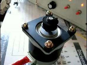
Although the circuits seem simple, a detailed project is controlled from the parallel port of the computer. The circuit built on the 74LS04 is isolated with 4n26 opto couplers and powered by IRF1010E Mosfets. The parallel port is the port that allows to manipulate the stepper motors in any desired variable such as speed, position and direction.
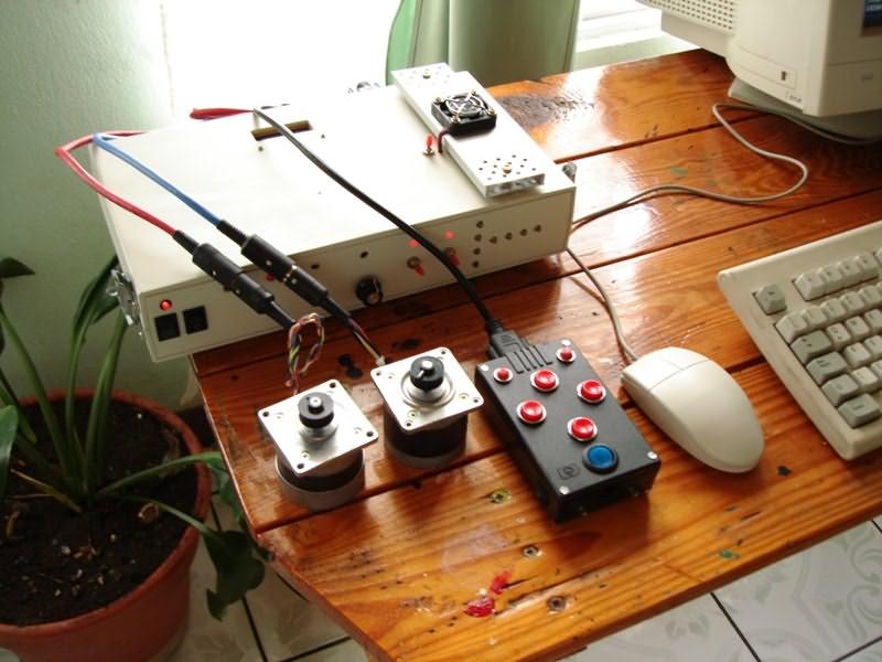
Although there are minor errors in this process, in general and for example, if a command is sent for the motor to move 500 positions, this is what actually happens, that is, the encoders that report the position from the motor to the pc are optional. and only required if you want to move the telescope manually.
The parallel port of the PC processes 5V AC signals at such low power that this type of circuit is required to handle the high power required by stepper motors.
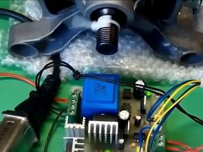
L298 Stepper Motor Driver Circuit test
If low-resistance motors (2 Ohms or slightly less per phase) and 12V are used, in most cases you can bypass the current limiting circuit without sacrificing much system functionality.
In this case, the circuit to be used will be as follows:
In either case, it is always necessary to verify that the motors are de-energized when the system is not in use because if these and the parallel port outputs are constantly on, the motor will become damaged over time due to overheating. This situation gets worse when all parallel port outputs remain open at the same time, which is very likely if the computer running the engines is running Windows, because it is not possible to know whether the parallel port outputs will remain open. From here we get one more reason to use the monitoring circuit.
L298 DUAL FULL BRIDGE DRIVER

The L298 is an integrated monolithic circuit in a 15- lead Multiwatt and PowerSO20 packages. It is a high voltage, high current dual full-bridge driver designed to accept standard TTL logic levels and drive inductive loads such as relays, solenoids, DC and stepping motors. operating . supply voltage up to 46 v .total dc current up to 4 a .low saturation voltage .overtemperature protection logical “0” input voltage up to 1.5 v (high noise immunity)
Source: mantsoft.googlepages.com/ PC Controlled Stepper Motor Driver Circuit pcb schematic alternative link:


Computer Controlled 8-Channel Dimmer Circuit 200W AT90S2313P
AT90S2313P 200 watt dimmer circuit is controlled from RS232 port with MOC3021 opto isolated triac driver control program running on xp pretty simple hex to asm code pcb diagram AT90S2313P There have also dosyalarıda pc program source code. rs232dimmer.asm, rs232dimmer.hex, dimmer.vbp, dimmer.vbw, dimmer.frx
PC Controlled Dimmer Circuit