It is a very interesting circuit compared to the combination lock circuits shared before. The heart of the circuit is the button, keypad, etc. for PIC12F675 microcontroller password entry. not used. The system works according to the impacts that occur with the impact. The piezo buzzer converts the magnetic vibrations generated by the beats into electric current. With the analog digital converter of the PIC12F675 Microcontroller, voltage information is processed and output is given accordingly.
The microcontroller used is just an 8 pin PIC12F75, which is more than enough for this project. A simple piezoelectric buzzer is used to capture doorbell sounds. It is easy to find and inexpensive as it is produced in various sizes. 20mm diameter piezo is used in the circuit. When it receives mechanical vibrations on its surface, these turn into electric current. The PIC detects this small voltage in the pulses using the internal analog/digital converter on the 2nd channel (an2).
The program running on the PIC detects and counts the time between the beats to be generated. This information is saved in the internal EEprom and then used to compare with user accesses.
It is unlocked by activating a relay that will open an electric lock when the correct password is entered. The activation time is set to 5 seconds and can be changed in the program.
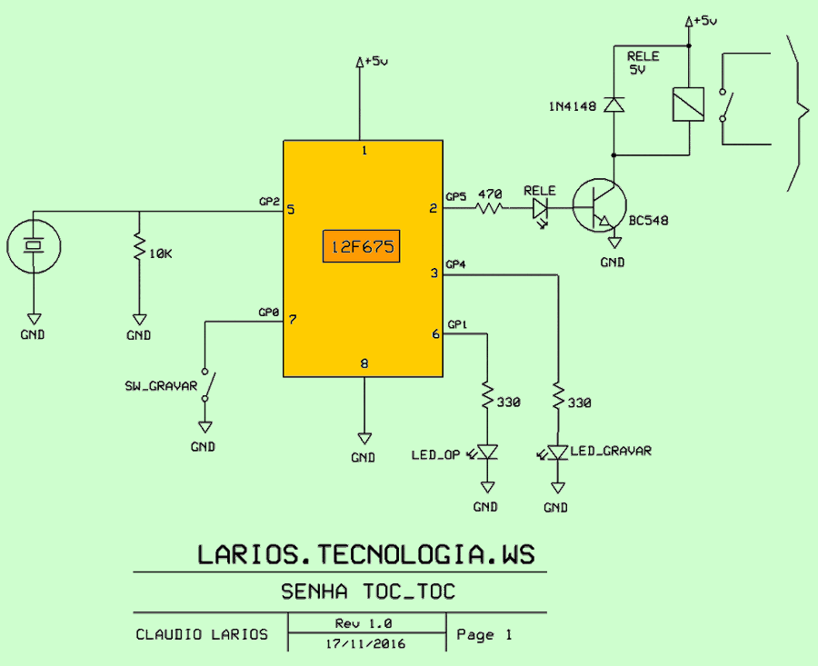
Knock Combination Lock Circuit Schematic
Apply voltage to the circuit and press the button on pin 7. The recording led on pin 3 will light up. Enter the password by hitting it in the order you want. Wait for the recording time to expire and the leds to turn off.
Enter the password to confirm the registration was successful. The program allows time tolerance, but is relatively small.
The password can be saved with a maximum of 20 strokes. However, long passwords are very difficult to repeat in a timely manner. So choose one with 5 or 6 beats. The maximum time between one hit and the next cannot exceed 3 seconds.
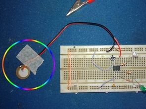
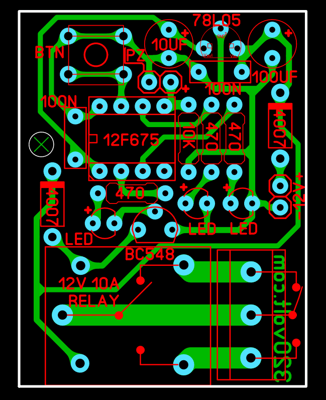
Note: I installed the combination lock circuit on the bredboard. PCB design checked but not tested. To use 12v in the circuit, a 78L05 regulator has been added for the PIC12F675 5v source. You can use a 12v 10A relay.
PCB, schematic, code files ; 28753a.rar pass: 320volt.com


