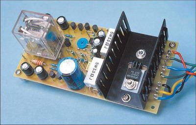
The speaker protection circuit prevents the speaker from burning as a result of DC voltage output as a result of any malfunction in the amplifier circuit, it also connects the speaker to the amplifier delayed and provides fan control, in addition, it disconnects the speaker when there is excessive temperature with the thermistor connected to the amplifier cooler. The speaker protection circuit works with 12v. LM317HVT is used for regulation.
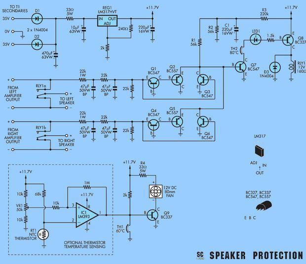
Since the power supply of the protection circuit is provided through the amp supply transformer, the amplifier is symmetrically fed, so a mid-ended transformer with 2x35v ac output is used. If the transformer you will use with a resistor is 2X24V, there is no need to use this resistor.
In addition, there is an LM393 op amp control circuit that controls the cooling fan according to the temperature rise in the cooler. NTC 1k…10k connected to the cooler can be used. You may not use this circuit as it is not a whole with the protection circuit.
If you can’t find the 47UF BP capacitors in the electrolytic but non-polar market, you can connect 2 100uf capacitors in series and use them.
Speaker Protection Circuit Diagram
Source: http://www.siliconchip.com.au/cms/A_103286/article.html
Speaker Protection schematic Fan Control Circuit PCB alternative link:


Car Speed Alarm Circuit Display Indicator PIC16F84A
speed alarm circuit PIC16F84A microcontroller used in the project’s source code, schematics and PCB files are there.