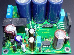
The dimensions of the PCB board are 80×80 mm. Each board is equipped with its own protection device that disconnects the load in emergency situation (appearance of constant voltage at the output or breakage of any of secondary windings of the power transformer), as well as performing the necessary load connection delay when power is applied. I found the work of the protection scheme proposed by the author unsatisfactory, and the scheme this node is different. In particular, measures have been taken to turn on the device as quickly as possible. and turning off the relay, which is important when the relay switches a circuit with a significant current.
The next important change concerns the ratings of the resistor “bridge”, which turns the LM3886 into a powerful current source. Reducing the “output” value resistor up to 0.2 Ohm made it possible to gain an additional power reserve of 4-5 W and use a much more compact resistor of lower power and with less own inductance. So, during tests, the amplifier was able to provide 68W output power (into 4 ohm load), before limiting output voltage by the oscilloscope. Of course, for a short time.
Due to the increased requirements for other “bridge” resistors, they were chosen from the special precision TanFilm series (thin film nitride based tantalum).
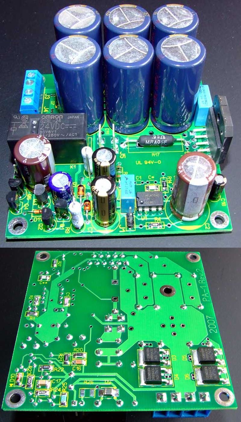
Changes in food chains are quite significant. As before, the board is equipped with rectifier with filter capacitors. Here I used Schottky diodes,
conveniently located on the underside of the board. and as filtering
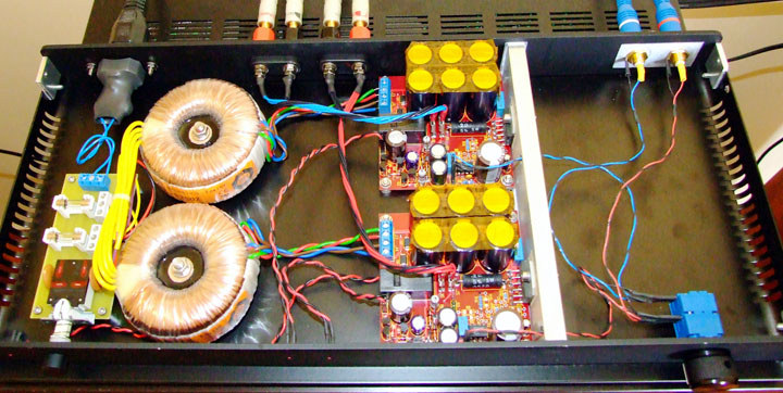
The amplifier should be powered from a power transformer of sufficient power (at least 50 VA) with two separate secondary windings of 22 or 24 V.
This is a typical rating and such transformers are easy to find. Preferable series with reduced induction, such as Amveco Magnetics, Nuvotem, Talema. The beginning of the windings should be connected to the same inputs of the terminal blocks J3, J4. It is possible to use a secondary winding with a midpoint, then this conclusion connect to any of the two “middle” inputs of the terminal blocks J3, J4.
The use of a transformer for output voltages less than 22 V is also possible. In this case, it may be necessary to change the values of the damping resistors R8, R9, R19. Monoblock design assumes separate power transformers. If necessary, you can use one common, double power. In such In this case, both boards are simply connected “in parallel”. Each board must be equipped with a heatsink of sufficient efficiency, or one common. Its efficiency determines how much useful power can be received before the start of operation of the thermal protection system built into the LM3886.
Some results of performance measurements
Gain in band 20
Hz – 20 kHz: 30 (+29 dB)
Maximum input voltage: 0.775 V p.
Frequency Response Band, -3 dB: 1.5 Hz – 90 KHz
Frequency response in the range 20 Hz – 20 KHz: no more than 0.2 dB
Phase response in the range of 20 Hz – 20 KHz: linear
Phase shift at a frequency of 20 kHz: -18 deg
GVZ in the range of 50 Hz – 20 KHz: constantly
Short-term power into 4 Ohm load: 68 W eff.
Recommended operating power: up to 30 W eff.
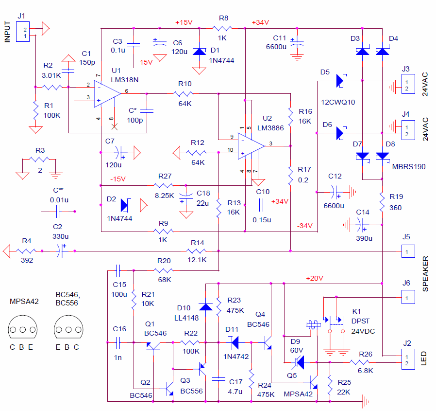
LM3886 Amplifier Circuit Schematic
FILE DOWNLOAD LINK LIST (in TXT format or file): 26669b.rar pass: 320volt.com


