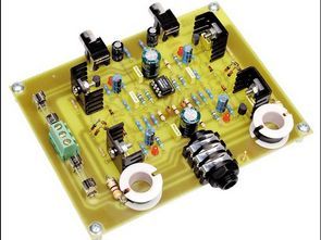
The Studio series is a premium stereo headphone amplifier with very low noise and distortion. Operating voltage installed on circuit OPA2134 opamp symmetrical + -15v dc
Headphone Amplifier Main Features
High performance – very low noise and distortion
Can be used with high and low impedance headphones
High output power (200mW; up to 8Ω and 32Ω)
Measured Performance values
Frequency response: from 10Hz to 20kHz
Nominal output power: 200mW 8Ω and 32Ω, 85mW 600Ω
Max. output power (current or voltage limited): 575mW 8Ω, 700mW 32Ω, 130mW 600Ω
Harmonic distortion: typically .0005% (600Ω load), 001% (32Ω load) and .005% (8Ω load)
Signal-to-noise ratio (A-weighted): -130dB (600Ω), -120dB (32Ω) and -111dB (8Ω) based on 100mW output power.
Channel interference: better than 20Hz-20kHz -68dB at 100mΩ output power
Input impedance: ~ 47kΩ || 47pf
Output impedance: ~ 5Ω
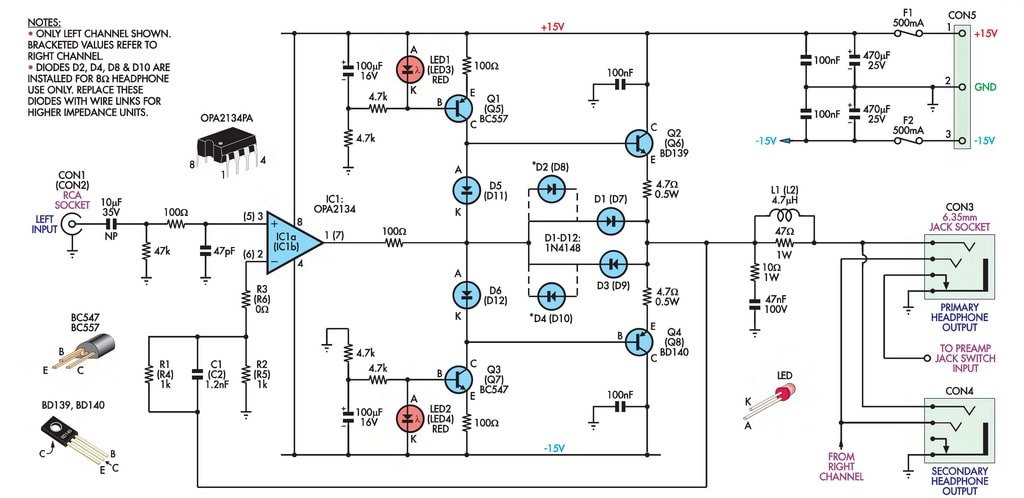
If you are going to use the headphone amplifier with an MP3 player, CD player, or a device with a preamphy, replace the 0-ohm (jumper) resistors connected to pins 2 and 6 of the OPA2134 IC with 2k.
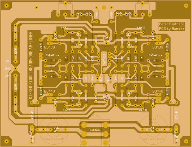
Coils of L1-L2 will be wrapped with a wire of 0.6… 1mm thickness, approximately 21 tuft. PCB drawing of Stereo Headphone Amplifier has source file prepared with sprint layout program.
Hi Fi Headphone Amplifier Circuit Diagram
Source: forum.cxem.net
FILE DOWNLOAD LINK LIST (in TXT format): LINKS-26638a.zip


Circuit d’amplificateur de casque stéréo Hi Fi
La série Studio est un amplificateur de casque stéréo haut de gamme avec un bruit et une distorsion très faibles. Tension de fonctionnement installée sur le circuit OPA2134 opamp symétrique + -15v cc
Caractéristiques principales de l’amplificateur pour casque
Haute performance – très faible bruit et distorsion
Peut être utilisé avec des écouteurs à haute et basse impédance
Puissance de sortie élevée (200 mW; jusqu’à 8Ω et 32Ω)