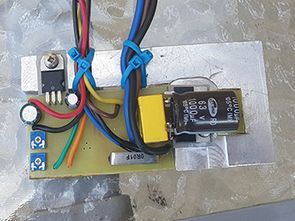
350W Scooter of Electric Motor Scooter control unit, max. It can power 500W. Input voltage 36V DC (can be used with 20V… 50V.)
Scooter Motor Control works on the principle of motor winding as a switched power supply and coil. In forward driving, the unit acts as a downstream converter and controls the current to the motor winding by PWM modulation so that it also controls the starting torque of the motor, this regulation is required. When recovering, the unit acts as a booster converter and motor coil as a choke.
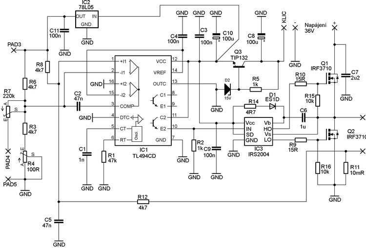
Scooter Motor Driver Circuit PWM Control At the output made with TL494 IC, 2 IRF3710 mosfet are controlled with IRS2104 mosfet driver. Current detection is done on 10mR 5W metal shunt resistor.
R4 can set the maximum motor current in the range of about 5A… 20A. R7 adjusts the acceleration and recovery (motor brake and battery charge) ratio.
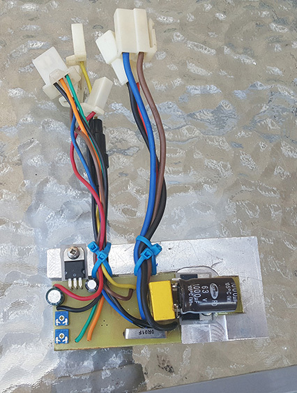
In the diagram, the terminal named “KLIC” will be connected to the Scooter switch box and the circuit will work when + 36V is applied to this terminal.
It is possible to connect a conventional potentiometer or a controller with Hall probe for control. Maximum power of the unit is about 500W
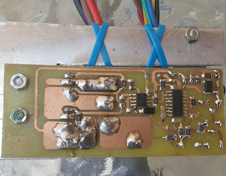
The circuit has a layout, PCB, diagram drawing and material list.
Scooter Motor Driver Circuit Diagram
Source: hobbyelektro.eu/zdroje-menice_kolobezka.php
FILE DOWNLOAD LINK LIST (in TXT format): LINKS-26634a.zip


Circuit de commande des moteurs de scooter 500W TL494
350W Scooter de l’unité de contrôle du moteur électrique Scooter, max. Il peut alimenter 500W. Tension d’entrée 36V DC (peut être utilisée avec 20V… 50V.)
Le contrôle du moteur du scooter fonctionne sur le principe de l’enroulement du moteur en tant qu’alimentation et bobine commutées. En marche avant, l’unité agit comme un convertisseur en aval et contrôle le courant vers l’enroulement du moteur par modulation PWM afin qu’il contrôle également le couple de démarrage du moteur, cette régulation est nécessaire. Lors de la récupération, l’unité agit comme un convertisseur d’appoint et la bobine du moteur comme un starter.
Contrôle PWM du circuit de commande du moteur du scooter À la sortie réalisée avec le TL494 IC, 2 mosfets IRF3710 sont contrôlés avec le pilote mosfet IRS2104. La détection de courant se fait sur une résistance shunt métallique 10mR 5W.
R4 peut régler le courant moteur maximal dans une plage d’environ 5A… 20A. R7 ajuste le rapport d’accélération et de récupération (frein moteur et charge de la batterie).
Dans le schéma, la borne nommée «KLIC» sera connectée au boîtier de commutation du scooter et le circuit fonctionnera lorsque + 36V est appliqué à cette borne.
Il est possible de connecter un potentiomètre conventionnel ou un contrôleur avec sonde Hall pour le contrôle. La puissance maximale de l’unité est d’environ 500 W
Le circuit a une disposition, un PCB, un schéma et une liste de matériaux.
Schéma du circuit du pilote de moteur de scooter