9 seconds display timer circuit
Contents
- 1 9 seconds display timer circuit
- 2 Schmitt trigger connected to the turn-off time relay type
- 3 555 audio tone generator integrated circuit
- 4 Ldr 555 audio tone generating circuit in the light
- 5 566 Square, Triangle Oscillator Circuit Signal Generator
- 6 Capacitive thyristor automatic stop
- 7 The light modulator circuit
- 8 Transistor turn off time relay
- 9 Sine wave generator circuit LM1458
- 10 With the inductive method, December (distance) measuring
- 11 Tureng circuit running in the dark
- 12 4-phase driver circuit for step motor
- 13 LM317, according to NTC temperature motor speed control
- 14 Thyristor DC – AC Converter circuit
- 15 ICL8038 Square Triangle Sine signal generator Oscillator Circuit
- 16 7400 NAND gates flip-flop circuit
- 17 CD4047 2N3055 High Current Output DC-AC Converter circuit
- 18 Transistor adjustable resistor (rheostat) to be used as
- 19 simple circuit that detects the soil moisture
- 20 Powered by the cut of the wire, the alarm circuit
- 21 A simple transistor circuit preamplifier
- 22 555 timer circuits
- 23 555 integrated Ultrasound receiver circuit
- 24 555 infrared transmitter integrated circuit

Display timer display circuit “””timing circuit NE555 CD4017 LED indicator 9 seconds” counter cd4511 CMOS circuit for the display relay output circuit BDC has developed a bit more again added the devices that connect to the relay contacts can be controlled.
Schmitt trigger connected to the turn-off time relay type

The transistor Schmitt trigger connecting briefly be explained as follows: the voltage that is applied to the relay immediately if it does not reach zero or the maximum value, generated by the magnetic coil of the relay will be insufficient, since the contacts will vibrate. This relay circuit is not required. Because serare vibration (spark) will cause deterioration of the contacts of the relay as quick reasons. Vibrations to a minimum value of relay contacts in transistors schmitt (bagels) is connected as the trigger.
Schmitt trigger turn-off timer circuit works like this: when energy is applied to the given circuit C is empty because T1 yet engaged in the sector. Therefore, at the end of the collector of T1 (a point) is at a maximum level according to the voltage value of the chassis. Hence the relay transmission by switching to T2 immediately and the buyer takes works. That are starting to be charged via pot R1 and C, after a while, his T1 transmission puts. The collector of the first message T1 (a point) and decreased voltage Emitter resistor R3 which is connected to what (point b), The voltage rises. This transistor T2 (due to the two electrical domain) into the cut which causes them to go quickly.
That is to say:
1. The voltage at the collector of T2 to T1 falling into the cut leads.
2. The resistor R5 is connected to a voltage of the order of T1 and T2, T2 will have the effect of reducing the flow of the white. (negative feedback)
If C is empty, since the B button is pressed in the circuit, T1 goes into the cut immediately. This is the collector of T1 (point a) causing the voltage to rise which puts the transmission at T2. As a result, the Schmitt trigger method as the relay transmission, or allows you to go very fast into the cut.
555 audio tone generator integrated circuit

the tone of the sound produced sound generator in the circuit, R1, R2, or by changing the value of C can be adjusted.
Ldr 555 audio tone generating circuit in the light

light, sound-generating circuit can be fed with a DC voltage between 5-18 V DC. The environment in the light of the circuit starts to produce sound. The sensitivity of the circuit can be adjusted with the pot. With pot if you changed the location of the sound generating circuit LDR in the dark will be made.
566 Square, Triangle Oscillator Circuit Signal Generator

566 used in the oscillator circuit called a voltage-controlled oscillator integrated with L1 or changing the value of C1 the frequency of the signal produced from the voltage change in the case of number 5, produces a different frequency output.
Capacitive thyristor automatic stop

DC-powered circuit of the thyristor for stopping the method that is used. in the given circuit S1 is pressed, SCR1 is the message. Scr1 with conducting, capacitor C starts to fill slowly through R2. After a while, the button S2 is pressed, the message scr2. Scr2 transmission of electric charge accumulated on C as the inverse polarir scr1 SCR2 with the passing over. Reverse-biased if the lamp extinguishes scr1 by cutting.
The light modulator circuit

According to the severity of the broadcast music or audio circuits are improved to light the lamps. As an example, a given thyristor circuit resistor and capacitor connected to the end of the three g values are different. In this way, each transmission is going to separate the value of the thyristor. Frequency bass signals to the circuit under the flow of scr1 400 Hz, 400 Hz-2 kHz psychic-frequency signals scr2 flow, the flow of the treble frequency signals above 2 kHz scr3 takes.
Audio frequency transmission thyristors switches according to the value of the signal from the amp. In this way, the rhythm of the music and flashes the lamps in accordance with a beautiful view is obtained. The old tube radios of the output transformer is the transformer in the circuit. The end of the W amplifier output transformer 4 to 5 kW of the electronic circuit is connected to the secondary ends. Today, this circuit works better optokuplorlu models have been developed.
Transistor turn off time relay

When you turn off the relay immediately when button C is pressed in the circuit will be charged. Transistor T1 of the electric current in excess of accumulated C will take that. When transmitting T1, T1 via the transistor T2 of the oval (- ) by taking the transmission of this element allows it to pass through.
The trigger transistor T3 to be conductive to the flow of beyzi T2 of the conductive element also enables to be a good reason to leave this as is. T3 when transmitting, the relay contacts by closing the receiver runs. The electrical load on the capacitor after a while ending in T1, T2 and T3 causes the transistor to go into cut. By connecting a pot in parallel with the capacitor in the circuit 500 pound it is possible to change the operating time of the receiver.
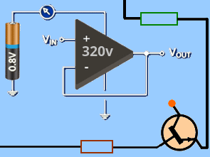
Sine wave generator circuit LM1458

Sine wave generator circuit LM1458 op amp made with The op amp is 6v…15V DC working with the number 7 in the leg retrieving the output in sine
With the inductive method, December (distance) measuring

The magnet in the coil move back and forth in the diagram given, if the inductance of the coil and reactance values vary. The current through this coil changes. The change in current associated with the integrated circuit through the coil quoted by sensitive analog circuits or digital display it is possible to run and measure the distance. Inductive approach with the detector op-amp of the expulsion: when a metal object approaches the sensor element at the lower end of a movement is born. This current is formed on the resistor R1 voltage op-amp output voltage level changes.
Tureng circuit running in the dark

the circuit running in the dark: LDR increases the resistance of the circuit environment is dark, and the tension grows from falling over. Falling on the LDR the voltage V reaches a value of 20-50 Tureng transmission through the lamp burns. LDR on the environment in light of the resistance decreases the voltage drops. This puts the Qur sector.
4-phase driver circuit for step motor

In the form of a square wave generated by the 555 circuit triggering the drive in with the police, named 4017 ring (ring) integration of the counter
LM317, according to NTC temperature motor speed control

The speed of the motor with respect to temperature changes of the circuit when the ambient temperature increases, the NTC resistance decreases and current flow through the pot increases. The increase of voltage increases the current that passes through the pot on this element.
Lm317 output voltage of the pot increase the voltage will increase and the number of rotations of the motor also increases. When the ambient temperature is LOW, the current flow through the pot and increases the resistance of NTC decreases. The reduction of the current that passes through the element reduces the voltage on the pot. A decrease in the voltage of the pot lm317 output voltage lowers, and the rotation of the DC motor speed is reduced.
Thyristor DC – AC Converter circuit

A pulse generator that is used to trigger the SCR in the circuit, should be ujt, 555, transistorized astable (unstable) multi-vibrator etc. you may be. Working with thyristors with capacitor c the DC supply circuit is stopped.
The pulse circuit puts the transmission in the order of the thyristor. When transmitting electric charge accumulated on C SCR1 scr2 puts the sector. After you come this time, C will charge in the other direction. When it comes to triggering to scr2, this element is the message. When transmitting the electrical load scr2 C scr1 puts on the sector. In this manner, the circuit keeps running. The currents flow in both directions through the middle trio is wrapped in the primaries, which generates the secondary AC voltage.
ICL8038 Square Triangle Sine signal generator Oscillator Circuit

ICL8038 can produce a shaped signal integrated circuits used in three different named. The frequency of the signal produced by the circuit, distortion (distortion, clipping) may be replaced with the ratio of resistor.
7400 NAND gates flip-flop circuit

The two inputs of the gate and not at logic 1, becomes 0 V to 5 V output when the voltage of the end. Two input logic 0 at the output when 5 V is applied.
with the principle of operation of the circuit: let us assume that V 0 is the output of the gate N1. In this case, led1 turns on. The output of gate N1 0 V in order to be a logic 1 signal on the resistor R2 must be present. The charging of this capacitor C1 becomes possible.
The moment the capacitor C1 is fully charged, the current through R2 represent, since 0 V is seen in this element. The voltage of 0 V R2 V to be logic 1 and the output of gate N1 makes the led1 goes out.
1 will cause the output to begin charging capacitor C2 of N1 to be even. This creates a voltage on R3. N2 V voltage on R3 the output of a logic 0 makes that occurs. The output of N2 is 0 V led2 works. In this manner, the circuit keeps running. LED Mini relays are used instead of low flow in the circuit 5 V if periodically runs a system that can be created.(in this case, the 270 ohm in series with the LEDs connected in series must be canceled.)
CD4047 2N3055 High Current Output DC-AC Converter circuit

DC-AC Converter circuit can convert 12 V DC to 220 V AC. The frequency of the AC output from CD4047 integrated, which is connected between the number of named 2-3 feet can be adjusted by changing the value of the pot.
One of the primary windings of the transformer in the circuit the current flows through transistors used to be big powerful high. BD243C Transistors 2N3055 heatsinks must be connected.
Transistor adjustable resistor (rheostat) to be used as

Big, powerful buyers, the current setting of high flow and large-bodied reosta it can be done. But the rheostat and take up much space, and also consumes additional energy. However, on the basis of the pot and the transistor with the circuit board it is possible to control the current better. in the given circuit, the value of P is changed unless the trigger beyze outgoing current varies, and accordingly, by adjusting the current from C to E to the power of L is controlled.
simple circuit that detects the soil moisture

A piece of two-wire circuit to be measured is inserted into the soil moisture. The humidity of the soil is increased when the lamp lights. The sensitivity of the circuit can be adjusted such that white will connect with serial.
Powered by the cut of the wire, the alarm circuit

Were pulled out a thin wire in the alarm circuit when the current from the collector of T2 FROM t1 and T2 by switching the transmission to the relay begins to move beyzi runs. When the relay contact closes, the alarm begins to work.
A simple transistor circuit preamplifier

A fairly simple transistor circuit preamplifier 2sd30 piece was founded on. 12v 18v supply voltage between + 9V battery 220ohm resistor at the input is replaced with the value 680ohm whether it can be used.
555 timer circuits

the 555 integrated turn-off circuit with time relay, type: s of the receiver circuit 1-15 minute periods allows you to work for. When the button is pressed, the relay operates. After a while, since the discharge of the capacitor c, The relay returns to the former position. The operation time of the circuit, T = 1,1.R.C [S] is a measure of. In the equation, R: resistance (in ohms), C: capacitor (electrolytic) are quoted.

the 555 integrated circuit periodically running relay: the capacitor and resistor used in the circuit according to the value of the integrated output location it is time to change
can be adjusted.
555 integrated Ultrasound receiver circuit

In the given circuit, the ultrasound transmitter circuit 5 receives the ultrasonic sound emitted from a distance of 30 meters, converts them into electrical signals, and the relay raises runs.
555 infrared transmitter integrated circuit

555 integrated circuit is extremely simple. By changing the value of resistor R1, the number of square feet from the exit integrated 3 The frequency of the wave can be changed.
12V to 30V TL497 DC DC Converter Circuit (20v-30v adjustable)
DC to DC converter An example might be the soldering iron 24V or charging battery pack for aeromodelling, or even power a laptop. Described converter is able without special transformer (and just plain Air coil with inductance of about 30μH) to deliver an output voltage adjustable in range of 20V to 30V when the power consumption of up to 3A. Output voltage while stabilized and the maximum change in the traffic-load and full load is less than 200mV. Maximum output power is 75W. output ripple voltage does not exceed 500mV (measured peak-to-peak).
TL497 DC DC Converter Schematic Diagram
Elektronische Schaltpläne Teil 1