To reproduce the audible bandwidth, three speakers must be used to complete the audible spectrum, since a single speaker can not emit the frequencies; Between 20 hertz and 20,000 hertz, this audible band is divided into three speakers, like this: Woofer – Responds to low frequencies. Medium (MidRange) – responds to mid frequencies. Tweeter – reproduces high frequencies.
For each of these speakers to reproduce; only the respective frequencies, a circuit must be built, between the output terminal of the amplifier and each speaker, this circuit is formed of coils and capacitors, to restrict and separate the frequencies. This circuit is called the Frequency Divider or Crossover.
These frequency dividers are divided into several categories according to the number of forms (2, 3 or 4 ways). The crossover can have an attenuation value of the slope of 6, 12, 18 or 24 desibeles (dB) per octave.
Frequency dividers can follow an approximation of two types:
– Traditional Butterworth or Passive Filter used in Hi-fi sound,
– Linkwitz-Riley, Active Filter with superior characteristics compared to the Butterworth filter, preferably used in 4-way crossovers of 24 dB / octave.
The Frequency Dividers are made up of capacitors and coils (wire rolls), which attenuate the frequencies. The use of a single capacitor or a single reel gives an attenuation of 6 dB per octave.
The way to connect the component determines what kind of frequencies it affects. For example: A Series Condenser connected in the positive; which goes to the speaker, is responsible for attenuating low frequencies and letting high frequencies pass. In this way a High Pass filter is formed, while if placed in parallel with the speaker, a high frequency attenuation is achieved, allowing the low frequencies to pass. This would be a Low Pass Filter.
The operation of the coil is reversed than the capacitor. If we place a coil in series with the positive, the high frequencies are attenuated and only the low frequencies pass, and if we place it in parallel, an attenuation of the low frequencies is achieved.
A detail to keep in mind is that in some cases when using crossover, a phase signal is introduced, which can be compensated by inverting the polarity of the tweeter connection, in the case of a 2-way system, and the medium (Midrange), in the case of a 3-way system.
To feed a speaker or woofer, a Low Pass Filter will be used. (A single coil in series or a coil in series and a capacitor in parallel).
To feed a medium speaker, a High Pass and Low Pass Composite Filter will be used. (One coil and one capacitor, both in series).
To feed a tweeter, a High Pass Filter will be used. (A single capacitor in series or a capacitor in series and a coil in parallel).
Designing a frequency divider is not complex, because just by applying the formulas properly, you can calculate the values of the coils and capacitors. You can also get a good result if you have a good ear.
A crossover or frequency divider is not for use in any baffle. The design of the box, the type of speakers and the power, are factors to take into account when making a crossover.
We recommend using good quality materials, such as the magnet wire of the coils. It must be in good condition, with its varnish intact. The caliber is very important, the greater the diameter of the copper wire, the lower its internal resistance. Therefore there will be less dissipation or heat emission. This allows us to use our crossover with more powerful amplifiers.
In some cases the coils for medium and / or high frequencies can be air core or Hollow type with or without plastic or cardboard form. The quality of the signal is directly related to the quality and size of the coil.
The coils with Ferrite Toroidal core are smaller, but their disadvantage is to have a saturation current. The value of this saturation current must be at least twice the nominal value to avoid deterioration of the signal in the current peaks. There are also coils built into the housing of a transformer. These coils are generally of high values and their use is reserved for cuts of very low frequencies between 50 and 150 Hz. The most common coils are constructed with sheets of iron-silicon transformer, especially those that have the shape of (I).
The capacitors recommended for this use are polyester or metallic. The most suitable condensers are those of metallized polypropylene film, with a tolerance of 5%. The recommended voltage is 250 volts.
When we are going to calculate a bandpass filter, it is not necessary to take into account the impedance of the common loudspeaker or speaker. Normally, the normal impedance between 4 and 8 ohms is established. In theory the impedance should be constant, although this may vary according to the frequency. Each speaker has its own impedance curve, with its backgrounds, its beats and its peaks.
It is preferable that during the calculation of the filter we use the frequency of the impedance of the curve, provided by the manufacturer. Therefore, a speaker with a standard 8 ohm impedance can have an impedance of 6.8 ohms at a given frequency, or even 10 ohms.
Sometimes the result of the calculation gives values of components that do not correspond to the standard values that are achieved in commerce. We must choose the closest value, since a small tolerance is allowed. Be careful to be within the same range.
For the Coils, the commercial values are:
0.15 – 0.18 – 0.22 – 0.27 – 0.33 – 0.39 – 0.47 – 0.56 – 0.68 – 0.82 – 1.0 – 1.2 – 1, 5 – 1,8 – 2,2 – 2,7 – 3,3 – 3,9 – 4,7 – 5,6 – 6,8 – 8,2 – 10,0 – 12,0 – 15,0 Milli henry (mH).
It is also possible to take a coil of a value higher than the calculated one and eliminate some turns of wire to obtain the required value. If you have an inductance meter, use it to get a good result.
For the capacitors, the commercial values are:
1 – 1,5 – 2,2 – 2,7 – 3,3 – 3,9 – 4,7 – 6,8 – 8,2 – 10 – 12 – 15 – 22 – 33 – 47 at 68 Microfarads (uF ).
It is possible to place different values of capacitors in series or in parallel to obtain the exact value.
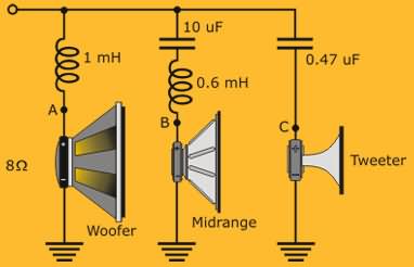
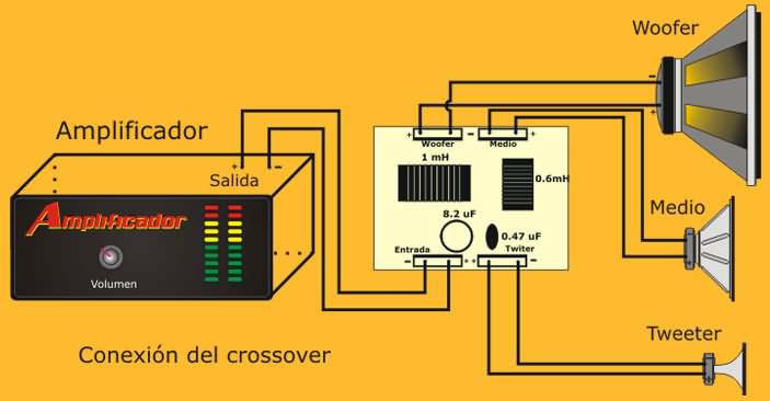
This diagram shows a typical passive Frequency Divider circuit. At point (A), the speaker or low speaker (Woofer) is connected. At point (B), the mid speaker is connected (Mid Range) and at point (C), the treble speaker (Tweeter) is connected.
It is observed that when placing a 1 mH coil connected in series with the Woofer, point (A), we will see how the voltage supplied by the amplifier has dropped to 70.7% in the 500 Hz, which is the lower cutoff frequency or minimum crossing and that in electronics corresponds to an attenuation of 3 decibels (dB).
Starting at 500 Hz, the woofer should not respond, as the mid-range speaker starts operating in series with a 0.6 mH coil and a 10-FU capacitor, connected at point (B), the The response of the average loudspeaker rises up to 5,000 Hz, which is the higher cut-off or cross-over frequency, since its voltage has dropped to 70.7% in relation to that supplied by the amplifier. Again we see how the signal has been attenuated in 3 decibels.
If the frequency supplied by the amplifier exceeds the value of 5,000 Hz up to 16,000 Hz, the tweeter; with a serial capacitor of 0.47 uF, point (C), it begins to reproduce the high frequencies. It is normal that these frequencies are not reproduced by the Woofer or the Medium.
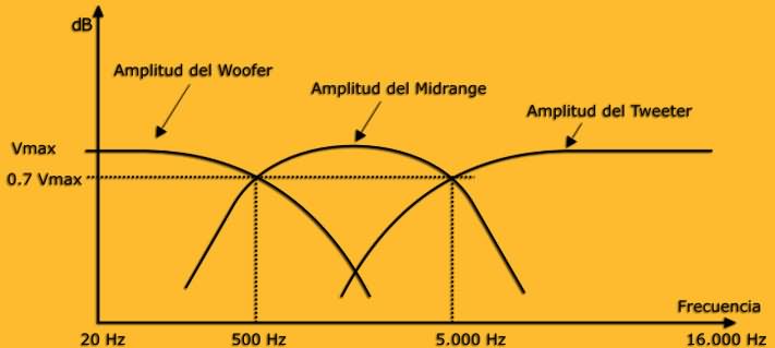
The bandwidth reproduced by the speakers is the result of subtracting 500 Hz from the Woofer (low), at 5,000 Hz from the Midrange speaker, obtaining 4500 Hz of the bandwidth of the Crossover circuit. It is necessary to clarify that the bandwidth; of 4,500 Hz in this case, does not mean that the three speakers only reproduce 4,500 Hz. On the contrary, the three speakers reproduce the entire bandwidth audible by the human ear, ranging from 20 Hz to 20,000 Hz.
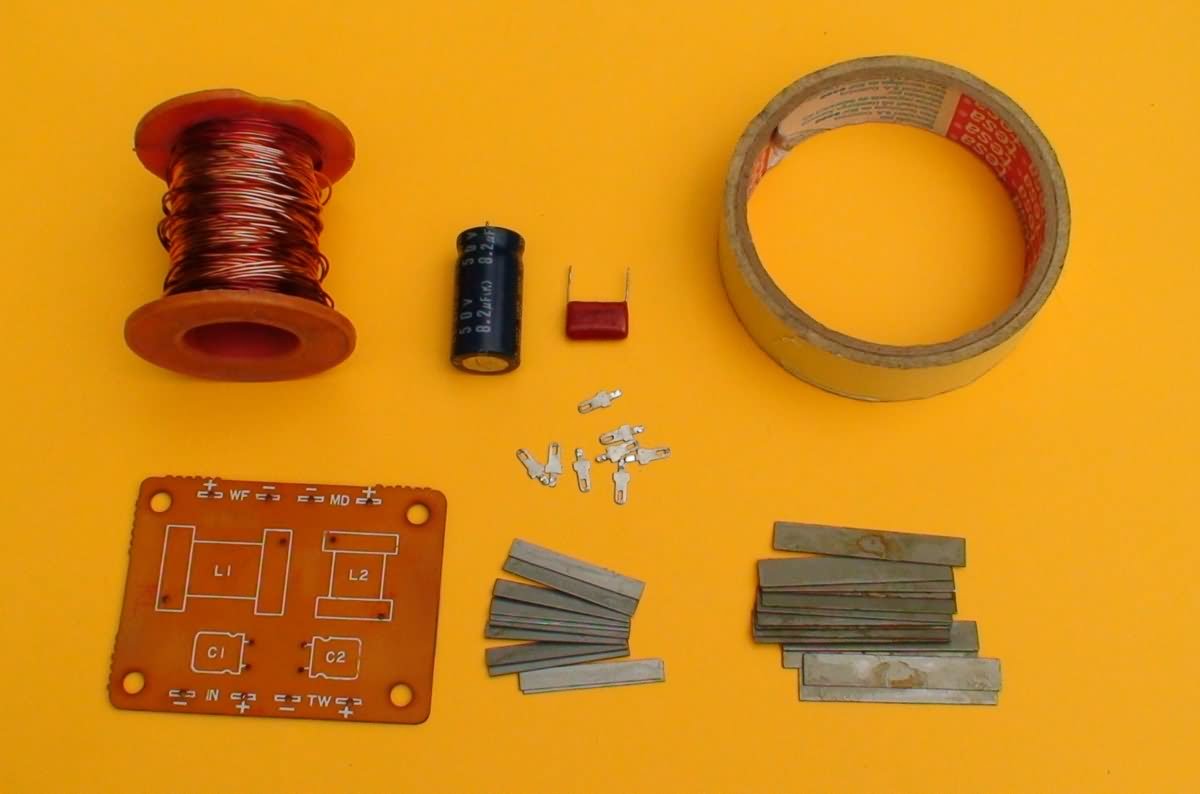
Crossover Materials
Contents
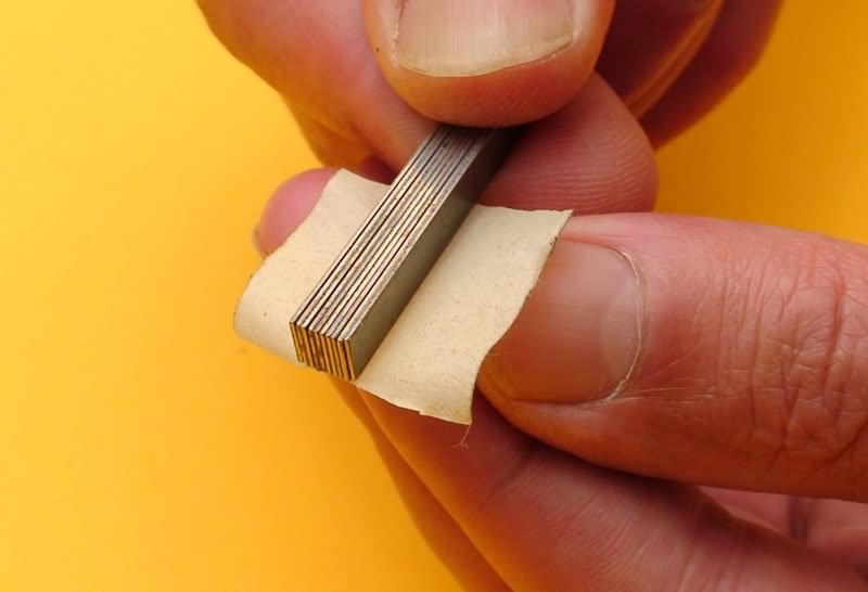
Core Armed
The sheets of Iron-Silicon used in the core of the coils, should be covered with two layers of masking tape or waxed paper. This is done in order to join them in such a way that they form a solid package and in turn, isolate them from the wire that will be later rolled up.
Winding Width
The printed circuit, can do it by the ironing method, if only going to do a pair of these, or with the screen printing method, if it is to reproduce it in an industrial way. If you plan to make circuits to sell, we advise you to send printed copies to pcbmicrocircuitos.com.
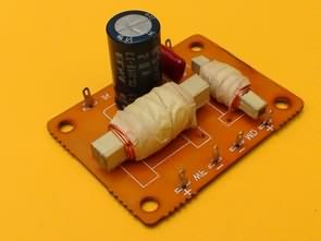
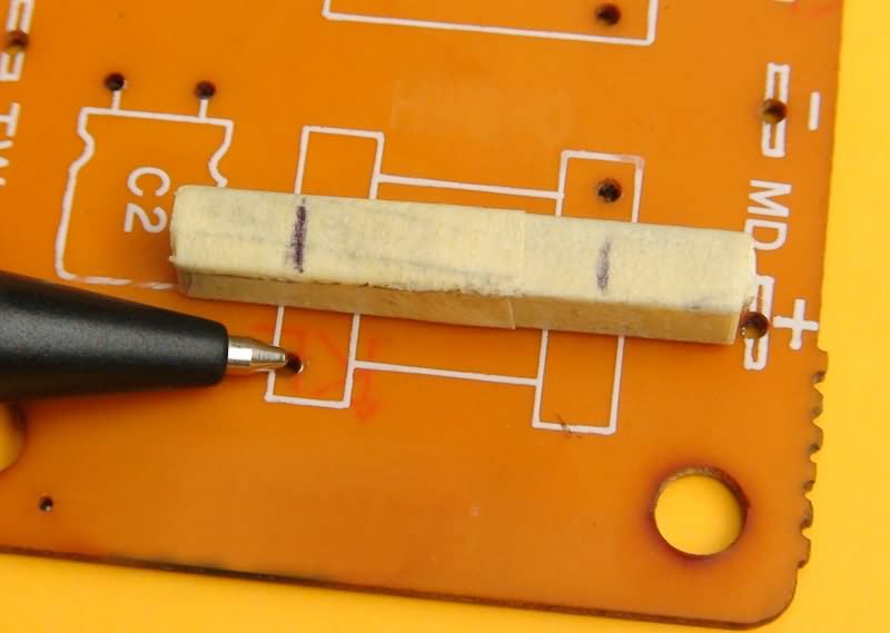
Once the form is done, we can use it as a guide, to mark the core, from where to where the wire will be wound. Observe the marks made on the tapered core, which coincide with the holes through which the ends of the coil wire will enter, where it points to the tip of the pen.
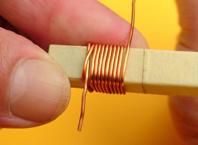
Knot and coil winding
It is very important to make the first round, leave the appropriate length of the tip to enter the card or printed circuit, the second round will be returned past the tip and taking the second round, making a knot like the one seen in the photo, each turn must be made thoroughly, since it is very important that the wire is properly adjusted.
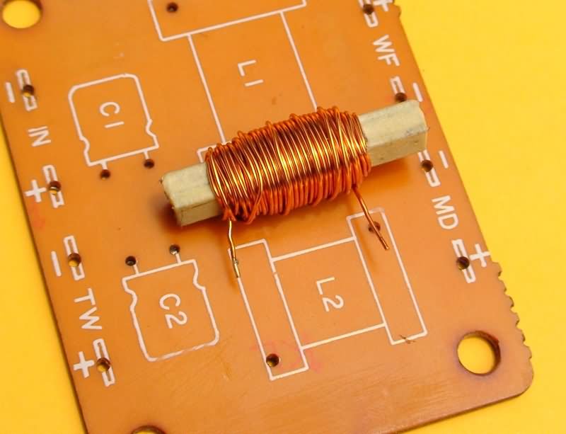
Winding measurement
When you finish winding the 3 meters of wire for the coil of the Midrange (Midrange) speaker, compare again with the form, matching the holes with the ends of the coil wire. Now build the Woofer coil with the larger sheets and the 5 meters of wire, repeating the same process as the previous coil.
If you want the wire to be more tidy, you can make a cardboard reel that will prevent the wire from expanding, to give a better presentation.
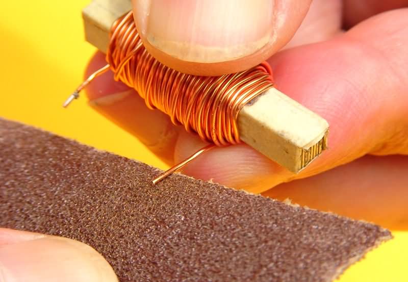
Removing insulation from the tips of the coils
Sand at the ends of the wire of each coil, only the fragment that will enter the printed circuit, removing the dielectric varnish, thus allowing the solder to adhere to the wire. Be careful not to scrape the coils and remove varnish more than necessary. Cover the outside of the coils with masking tape.
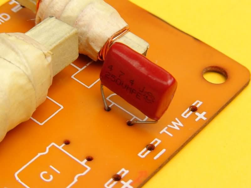
Capacitor Mounting Tweeter
Place the capacitor of 0.47 microfarads, which will restrict the passage of low and medium frequencies, so that the tweeter only reproduces the high frequencies. Keep in mind that not all tweeters are the same or of the same quality. In some cases we will find that the 0.47uF capacitor does not allow some tweeters to sound properly or simply lose volume. In these cases we should change the condenser to a higher one. For example, 1uF, up to 2.2uF. Remember that they should always be non-polar condensers and preferably polyester.
Midrange capacitor assembly
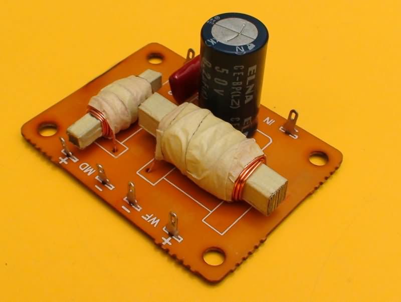
Place the 8.2 or 10 microfarad non-polar capacitor. If you do not get this capacitor, you can use two capacitors of 16 or 22 microfarads, connected in series by the negative poles and insert the two positive pins into the holes of the printed one. So you will get a capacitor of half the value of the two used and it will also be non-polar. If we plan to use this crossover with high powers (more than 100W RMS), it is better that the capacitor be made of polyester. Since the 8.2 uF capacitors in polyester are not very commercial, two 4.7 uF polyester capacitors can be placed in parallel to give 9.4 uF.
To finish, clean the form well on the side of the welds, using thinner and a recycled toothbrush.
This Frequency Divider has been tested with amplifiers from 30w to 400w that are in our projects section, obtaining good results. If your amplifier is stereophonic, you should build two of these.
To increase the power of the crossover thicker wire should be used. To achieve a change in the frequencies, more wire should be rolled and a larger core used. To achieve a deeper bass on the woofer, a non-polar 22 uF capacitor, connected in parallel, can be placed. (Between the positive and the negative of the woofer). It is best to investigate how to calculate a crossover.
Source: construyasuvideorockola.com
FILE DOWNLOAD LINK LIST (in TXT format): LINKS-26073.zip


Make Aluminum Amplifier Box
Make Aluminum Amplifier Box
Making an Amplifier is sometimes very challenging in the Amplifier. It is important for us to use easy-to-process material for the amplifier box, because the indicator, fan and so on. In order to have a fine workmanship for the sections, there is usually no equipment and materials suitable for these jobs in the amateur workshop.
Aluminum can be partially removed by aluminum in the cover sections if it is possible to make the aluminum Amplifier box skeleton using aluminum profile which can be easily machined. As in this study, welding, bending and so on. Aluminum project boxes can be made using aluminum profile, panel outside the amp, because it doesn’t need difficult operations such as
Amplifier box construction is started with box skeleton and aluminum profiles are cut and connected with screw with nuts. opening up the holes for how much input, output, indicator, visuality is so hard.
Aluminum Amplifier Box
all circuit daigram layar out only