Basically, if you want to make the battery centering device costs about £ 150 and it can do the job. I’ll talk about assembly with low voltage spot is doing is also very high voltage centered with which devices are, but the cost and effort in terms of low voltage better than me soon consider implementing a project I, but very high-capacity capacitor required, though the power supply you raise capacity as sorunuda disappears.
Materials required for the system to 12 volts dc power supply 1.5 farad capacitor 100 amp 40 volt thyristor metal type 1.5 volt battery left button pressed and copper probes
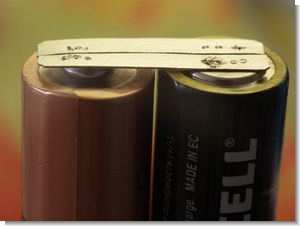
Battery Spot Welding System

Pens are used to trigger the thyristor battery with push button battery left out we spotted triggered thyristor voltage is transmitted to the metal. UPS device voltage in the cables should be very thick or thicker than the battery cable may be


In this project, a large power supply capacitor using a low-power capacity lower values kept examples you can use a different project in the same system 500w (estimated) Variac made using


Battery spot welding system more useful you can make table-type large drill as in the lifting and lowering the arm with a mechanical probes mount and Piller fixed tightly to hold “inhabited” and easier to spot drilling job can butonu table under the foot pedal as yerşeltir can.
You can also add a circuit with an electronic timer circuit thyristor can trigger an instant example the system is energized after 5 seconds will trigger the thyristors, etc. 2 ms. Guui is up to your imagination and skills
http://speleo.ru/phpBB3/viewtopic.php?f=31&t=533
http://www.ledhacks.com/power/battery_tab_welder.htm


Programmable Combination Lock Circuit PIC16F84
Prepared by: F. San – 1 relay control circuit pic-16f84 is based on the keypad’s LED indicators and buzzer alert source. Bass. Hex code and simulation files have isis proteus. Thanks to the people who contributed to prepare.
4 × 3 matrix form lock password is entered via a keypad connected. As soon as the circuit programmable lock password is 1234. Activate the relay output that is keyed to unlock and then # 1234 is printed. If the password error relay is energized. To change the current password, for example, in 1961: 1234 * 1961 # 1961 # to be monitored as a key sequence. Changing the password fails, the old password will remain valid.