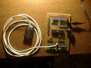
Atmel ATMega16 that you develop with projects to try to develop a multifunction test, development board LCD connector UART input LEDs display various adjustments for the dip switch and control buttons have an external 12 volt supply is working with also protel and sprint layout prepared by the source PCB files available
ATmega16 AVR experiment board

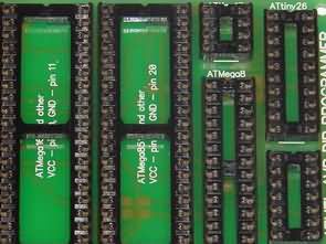
Microcontroller “Atmega16” and the socket for him. Be to, It would also require the 32 light-emitting diodes (3 mm), both also 1-2 K surface mounting resistance. Locking the scheme, the four 8-column connections. MAX232 chips the quartz resonator (4-16 MHz) RS232 and some external contacts.
Source: elektronika.lt// ATmega16 AVR Test Board for Beginners pcb schematic alternative link:
ATmega16 AVR Test Board for Beginners ZIP File Password: 320volt.com
AT89C51 DS1621 Thermometer Circuit
AT89C51 Operation of the thermometer circuit DS1621 temperature sensor circuit using a digital thermometer will tell if I made. As a simple circuit operation is as follows; The numerical value obtained from the temperature sensor, microcontroller, with the help of the I2C serial communication protocol, this value is sent to the LCD and the microcontroller will eat more if I basıyor.biraz 16-bit microcontroller receives data from the sensor to the LCD in interpreting transfers.
AT89C51 Thermometer Circuit Schematic