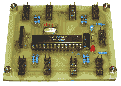
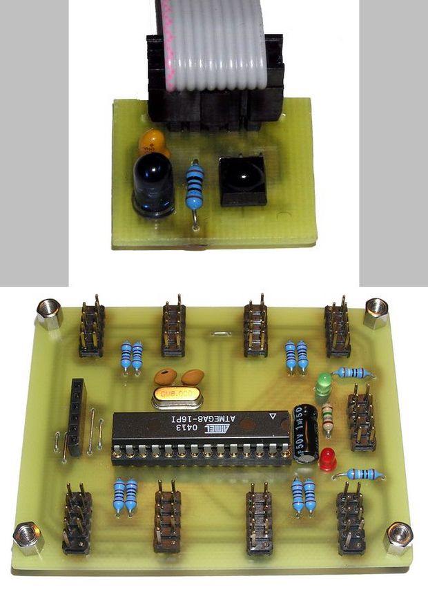
8 channel IR detector proximity sensor circuit is implemented with ATmega8 microcontroller. Obstacle sensing measuring via I2C bus (TWI, SMBus), designed for mobile robot. The Proximity Detector circuit works on the basis of reflecting infrared light beam.
Eight-channel proximity sensor information;
Measuring principle: IR light reflection Detection
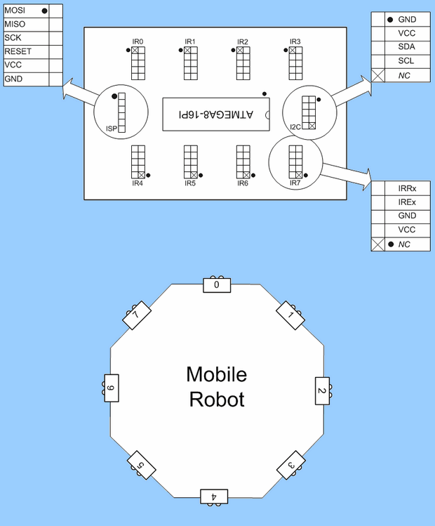
Max. Number of sensors: 8 independent sensors
Communication interface: I2C – 7bit address
Module size: 78 x 62 mm (3” x 2.44”)
Number of measuring degrees: 3 distance levels (Min, Mid, Max)
Supply voltage: +5 V (DC)
Current consumption: 15 mA
Microprocessor: ATmega8 ATMEL (AVR – 8MHz)
ATMEGA8 proximity dedector
Measurement principle
For measurement, detection of reflection (reflection) of infrared light from any obstacle is used. The wavelength of the light used is 940nm. The light is emitted by an infrared LED. The transmitted light beam consists of pulses with a frequency of 38 kHz to avoid receiving a parasitic signal that could cause false detection of an obstacle. The receiver is sensitive to this frequency, resulting in a reduced chance of error.
But this frequency is used to transmit remote control commands for household appliances. To eliminate the possibility of these drivers affecting the measurements, the control program is designed to respond only to the impulses it generates. Other received signals are considered false and not considered an obstacle.
The proximity detector can also measure the change in distance of the obstacle. This is achieved by sending pulses of different brightness intensities. In this case, the distance of the object is directly proportional to the level of the transmitted signal at which the reflection is recorded by the detector. This measuring principle provides only a few indicative steps of information about the approaching obstacle.
In no case can it be used for exact distance measurement, which excludes the fact that the signal level at which the reflection is detected is highly dependent on the reflectivity of the material from which the obstacle is made. This dependency is very strong and can make hundreds of percent difference when measuring. However, it can be used advantageously to record the change in distance of an obstacle. The intensity of the pulses is regulated using PWM.
Source: ir.babjak.cz/ IR detector circuit schematic source code pcb files alternative link:


Fuse Bit Generator Program Hi Tech C, Picbasic PRO Proton ide
Fuse code generator program of popular compilers, Proton, Picbasic and Hi Tech C software supports needed in microcontroller software prepared fuse (fuse) is designed to generate code. Able to produce the code necessary to microcontrollers and is currently under development.
PIC microcontroller supports a lot of PIC16F…. PIC10F.