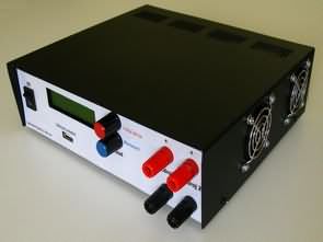
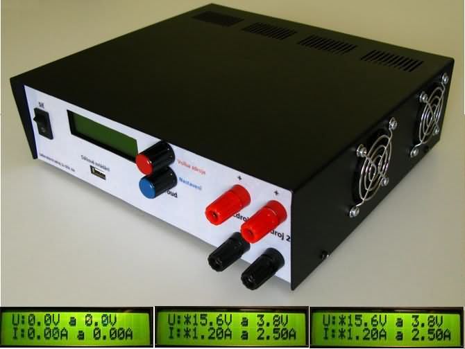
0-30V 0-6A Adjustable Laboratory power supply LCD Display ATmega16 controlled The basic involvement of the entire laboratory resources. Ac mains voltage 230V is transformed into two equal dc voltage 35V and also on the two voltage with a value of 5V for various polaritách. To a voltage of 35V is connected part of the Active cooling. All these strains lead to Regulatory blocks 1 and 2. You have the task to stabilize the input voltage and vary its size depending on the set value of the output voltage. They also contain the function of restricting the output current. Both of these electrical variables are set by using part of the Digital management.
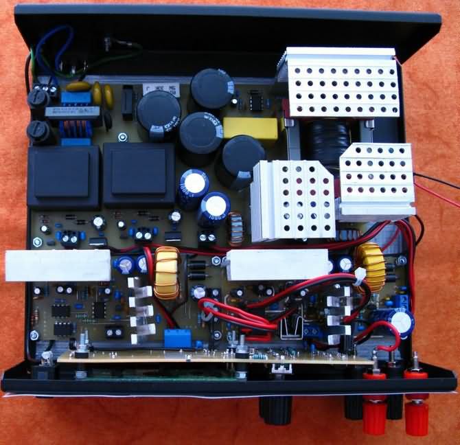
Power branch with a voltage of 35 V In this branch of the Network part of the source will be transmitted power to achieve values up to 490W, and therefore he was elected a switching power source type in the involvement of polomost (see. chapter 1.2.9). The switching of the power transistors is controlled by a smps circuit IR2153
This simple smps circuit can switch the power transistors connected to the inputs of the HI and LO when the voltage of 600v. But thanks to a stabilizing diode connected to pin VCC voltage of 15.6 V. Pins RT and CT is used for connection of external RC article, which with the internal circuitry of the IR2153
The task of the regulatory block is the stabilization and regulation of voltage and current. In order to achieve high efficiency, but at the same time and the speed of reaction to the change in the connected load, is the control block consists of two parts – switching and linear. The core of the switching section is an integrated circuit L4970 and the linear part of the circuit of the LT3081.
IR2153 Smps Circuit Laboratory power supply
The main control circuit is a 8 bit microcontroller ATmega16 from Atmel. In his holster conceals processor, 16 kB Flash, 1 kB SRAM, 512 B of EEPROM, four 8-bit ports, one 16 and two 8-bit counters, analog comparator, eight 10-bit a/D converters and other peripherals
![]() digital lab power supply circuit pcb schematic all files alternative links:
digital lab power supply circuit pcb schematic all files alternative links:
FILE DOWNLOAD LINK LIST (in TXT format): LINKS-25605.zip


Switching Laboratory power supply 0-30V 5A TL494 Buck Converter
Adjustable Laboratory power supply adjustable Voltage 0-30v adjustable current 20Ma-5A TL494 DC-DC Buck Converter high efficiency.
A PWM generator is used to generate budiaceho signal for spínanú control. As a source of PWM the signal is used, the integrated circuit TL494 PWM signal for switching of the upper trigger is created using the outputs C2 and E2. The collector (C2) is connected to 5V power supply, which is in introduced to the emitter (E2). For the regulation of the striedy PWM chip TL494 is used to input the DTC (Death Time Control) which is with control voltage from 0 to 3.3 V, making it jump regulation from 3% to 100%. This is rebound, not striedy, which means that the maximum output alternates is 97% in zero voltage at the entrance of the LIBRARY.
ATmega16 Digital Labor Netzteil IR2153 Schaltnetzteil LT3081 L4970
0-30V 0-6A Einstellbare Labor Stromversorgung LCD-Display mit ATmega16 gesteuert, Die grundsätzliche Mitwirkung der gesamten Labor-Ressourcen. Ac-Netz-Spannung 230V verwandelt sich in zwei gleiche dc-Spannung 35V und auch auf die beiden Spannung mit einem Wert von 5V für verschiedene polaritách. Zu einer Spannung von 35V angeschlossen ist Teil der Aktiven Kühlung. All diese Belastungen führen zu Regulatorischen Blöcke 1 und 2. Sie haben die Aufgabe, zur Stabilisierung der Eingangsspannung und variieren in Ihrer Größe je nach dem Wert der Ausgangsspannung. Sie enthalten auch die Funktion der Beschränkung des Ausgangsstrom. Diese beiden elektrischen Größen werden durch die Verwendung eines Teils der Digitalen Verwaltung.