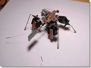
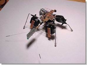
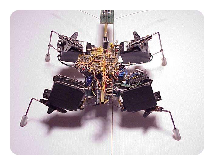
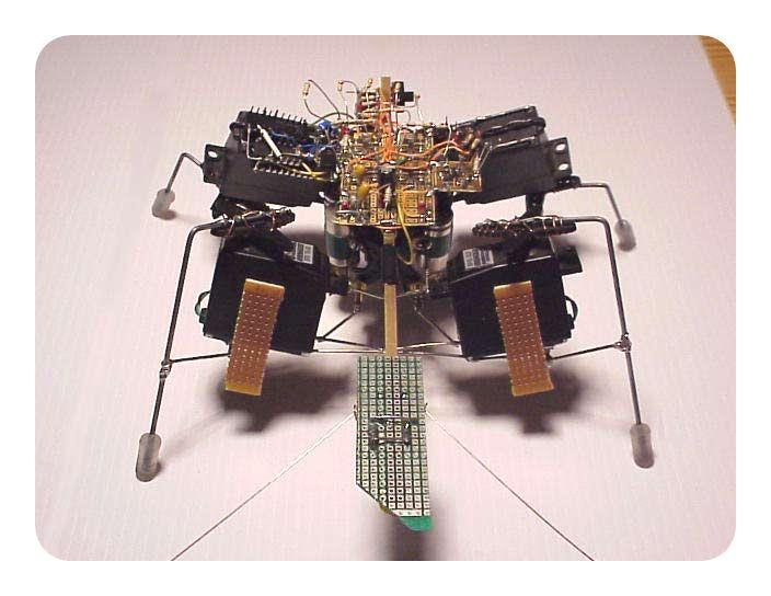
You don’t need a microcontroller to make a robot. A good example is how it worked in such a complex mechanical structure. A robot insect with a beautiful working leg. It is a five-motor walker that goes towards the light and avoids obstacles. The goal was to create a walker that could navigate uneven complex terrain while searching for the brightest light source. The base controller for the walker is dual core with four master/slave connections. All other circuits take input from the sensors and change the signal from the dual cores to back up, rotate the walker and seek light.
Walk forward by raising front legs Walk forward by raising hind legs Walk backward Deflected right ~2′ turning radius Left deviated ~2′ turning radius
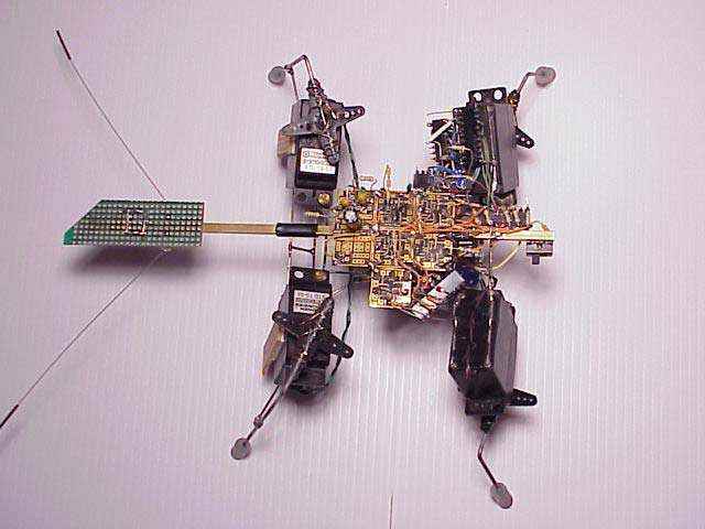
1. On-Off switch
2. Inverters to rotate the walker left and right.
3. The part used to control light seeking
4. Bicore. At this point it is not used for anything.
5. Bicores that control the legs.
6. Inverter causing Walker to roll back
7. Timer capacitor for backup.
8. Battery Changer (invisible)
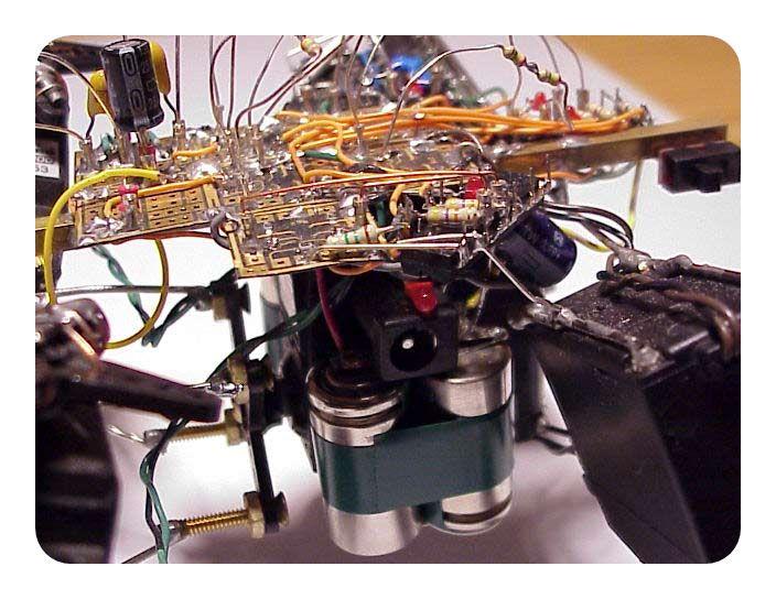
Notes: The only thing not shown are the motor drivers. I used two sets of three 74AC240 inverters in parallel to drive each servo. Any driver will work, so replace (M) with the driver you want. Here’s what mine looked like…
Insect robot design consists of several parts:
I) The light detector uses inverters from group F(2),J(2),K(1),L(1) and a 2 input AND gates to generate enable signals that control 3 output states: a. turn left b. turn right c. Go straight
II) The two main dual cores use inverters from groups B(2) and C(2) coupled with a 7.2M resistor so that the waveforms oscillate in quadrature with 25% overlap. These are connected to motor drivers (Ian used 6 74AC240 inverters for each motor) that control the two rear legs.
III) Two front motor auxiliary dual cores use inverters from groups D(2) and E(2) with timing components that delay the output of slave dual cores by about 25%. These are connected to the front leg motor drivers (6 inverters per motor).
IV) Two front motor reverser circuits and LED indicator use inverters from groups H(3), I(3) and are connected between the outputs of each master bicore (rear legs) and slave dual cores (front legs) to control rotation. with activation signals from the light detector circuit. When both reversers are closed, the walker moves straight.
V) A bel secondary dual core circuit uses inverters from group A(2) to control the bel motor drive (using six 240 inverters). Actually (as far as I know) this slave bicore is not needed at all (see VI).
VI) The bel inverter uses inverters from group G(2) and is connected between one output of each of the two main dual cores and the bel dependent dual core circuit at V. As far as I know the output of the inverter should be connected directly to the waist motor drivers. The waist reversal circuit is activated by one of two collision-triggered tactile switches.
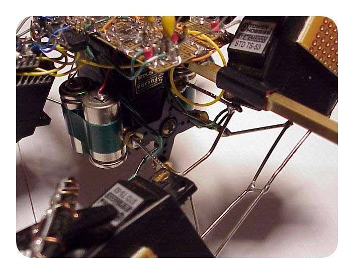
VII) The power supply consists of a 4.8V NiCd battery with on/off switch and a rectifier is included to charge the battery pack without removing it from the walker.
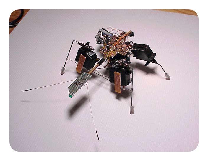
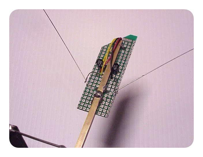
The light detector uses two photodiodes as a “photo bridge” to detect whether the light level is balanced or unbalanced on the two photodiodes. 2 photodiodes are connected.
Bug Robot Project


source : beam-online.com/Robots/vwalker1/index.html Bugs Robot alternative link:


Texas Instruments Electronic Calculator Programs
Texas Instruments has produced many integrated programs prepared for the calculations you can use online as offline, some works directly through the site some examples in excel format Shunt Regulator tl431 Design program are prepared for Office 2007 programs to run on, you must enable macros