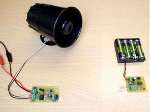
A simple alarm circuit but Mr. deterrent siren voice of the author would not last 🙂 circuits infrared transmitter and as a receiver consists of two parts transmitter circuit also 555 integrated with a controlled IR LEDs have a (tv remote control used in) LED signals sent by other circuits as well TSOP (38kHz or at 36kHz) signal reaches the receiver cut starts to work as soon as the siren siren plowed with TIP120 transistor to stop the alarm does not sound quite high-energize the circuit required

About one month ago I had a request to write about break-beam sensors. So, here it is!
Well, basically break beam sensor consists of two parts: transmitter and receiver. Transmitter emits light (it could be, for example, an LED or a laser) and that light goes to receiver. If that light beam between transmitter and receiver is broken by some obstacle, and receiver detects no incoming light even for a brief moment – it triggers an alarm (or any load you want). For example you can count people that entering some room, or you can use it as an alarm system, yeah, just like in movies!
First thing that comes to mind is to connect LED or laser to DC power supply on transmitter side, and use phototransistor with an amplifier on receiver side. But that is not gonna work with changing ambient light level. For example you calibrated your amplifier to work on a cloudy day, and then bright sun shined at it and in this case it won’t trigger an alarm because it already has sufficient level of incoming light.
But somehow TV remotes work under any ambient light conditions… It’s because they emit IR light with specific frequency. And TV receivers react only to that specific frequency. It means that it doesn’t care about slowly-changing brightness of ambient light, and reacts only on fast changing brightness level with some specific frequency. The frequency that TV remotes work at is usually 36kHz or 38kHz, but there is many other “standard” frequencies used in IR remote control applications. So, basically infrared LED on a transmitter side should switch on and off with that frequency.
For this purposes you can buy special receivers that react only on specific frequency. The most popular series of that receivers is TSOP
You’ve got IR transmitter on the right and TSOP receiver on the left, which is connected to microcontroller (instead of micro, you can put any low current load to it’s output).
This receiver only needs clean 2.5V to 5V input. So, R1 and C1 is just recommended (but not absolutely necessary input RC filter). R1 is usually 100(ohm sign) and C1 is 4.7uF.
TSOP output can sink up to 5mA load current (it can short to ground up to 5mA load). That’s sounds like not much, but hey, this receivers usually used for remote control, and not for working with high current loads.
As you can see it has two connectors. Power connector, and connector for infrared LED. As well as ON-OFF switch and reverse polarity protection diode.
555 timer can drive up to 200mA LEDs, which would be more than enough for about 30+ meters(100+ feet) range.
On the top there is 78L05 voltage regulator that provides 5V for TSOP IR receiver. On the left you can see connector for the receiver with some power filtering, which, I think, is unnecessary.
Latch is built upon two low power signal resistors. It’s all is really simple, TSOP opens Q1; Q1 then opens Q2 and then R4 keeps Q1 open making it a closed loop.
C4 in the latch section is needed to prevent latch closing on powering on the circuit, when TSOP output is still high.
After the latch is closed, it opens Q3 which turns on any output load (siren, water pump with hose in the face, etc… use your imagination )))
FILE DOWNLOAD LINK LIST (in TXT format): LINKS-19928.zip pass: 320volt.com
Source: jumperone.com/2011/11/break-beam-sensor/


Universal Microcontroller Development Kit
Very advanced microcontroller Developmentcircuit many features as well as different firms mikrodeneyleyici also supports some atmel try to set artificial der some microchip author for making a big difference all in one made :) on the circuit Atmel ATmega168, NXP LPC1114 and Microchip PIC18F453, PIC18F250 tested circuit Altium pCB desinger 10 has been prepared by drawing all the files under the user can give to the enlightened
Einfacher Tonalarmkreis mit ne555
Eine einfache Alarmschaltung aber Herr Abschreckung Sirene Stimme des Autors würde nicht dauern 🙂 Schaltungen Infrarot-Sender und als Empfänger besteht aus zwei Teilen Senderschaltung auch 555 integriert mit einer kontrollierten IR-LEDs haben eine (TV-Fernbedienung verwendet in) LED-Signale gesendet von anderen Schaltungen sowie TSOP (38kHz oder bei 36kHz) Signal erreicht den Empfänger Schnitt beginnt zu arbeiten, sobald die Sirene Sirene mit TIP120 Transistor gepflügt, um den Alarm zu stoppen klingt nicht ganz hoch-Energie die Schaltung erforderlich