TDA1554Q and LM1036 with the bass, treble, volume and balance controls can make high quality cheap complete amp circuit TDA1554Q supply and output options, thanks a lot, car radios, household, pc sound system is used in two integrated with 4x22w a cheap car amp can be
Key features
4x11w or two depending on how power can give x22w
Supply voltage is not symmetrical single-source
Lowest 6V – normal 14v – 18v dc highest
Mute, etc. stantby. There are a lot of features such as
Thermal, overload protection
Tone Controlled Amplifier Project
LM1036 is a very popular sound system used in the most important feature of an integrated stereo tone control dials do not have to use two channels with mono audio can be controlled potentiometers also “LOUDNESS” feature can reinforce low bass tones


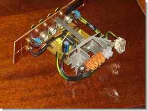
Presenting amplifier based on TDA1554Q application notes and circuits LM1036 The device very easy, he realizes that in this section, in addition to much more ambitious design seems to be debatable. Faced with the problem of supply columns in the workshop decided to submit amplifier: cheap, simple, with a small number of elements, powered by the 12V battery. Browsing the internet resources I noticed that a lot of young electronic engineers looking for this type of construction, meeting decided to present this simple design. The amplifier does not have a case and only the front panel which is bolted to the element table, sink, and strengthening. The panel is: power switch (12V), potentiometers, gain, bass and treble, balance,

source: elektroda.pl TDA1554Q Car Amplifier Circuit LM1036 Tone Controlled schematic pcb files alternative link:


Computer Controlled Home Automation Circuit PIC16F877 CCS C Visual Basic
Basic home automation project can be an example with all the resources INFINITY side @ picproj on the forums shared software ccs-c prepared by the source. C. H ccsc codes isis simulation files and visual basic interface of the control program. VLPs,. Frm,. VBW code’s pic and computer via the serial port using the supplied communication with MAX232.