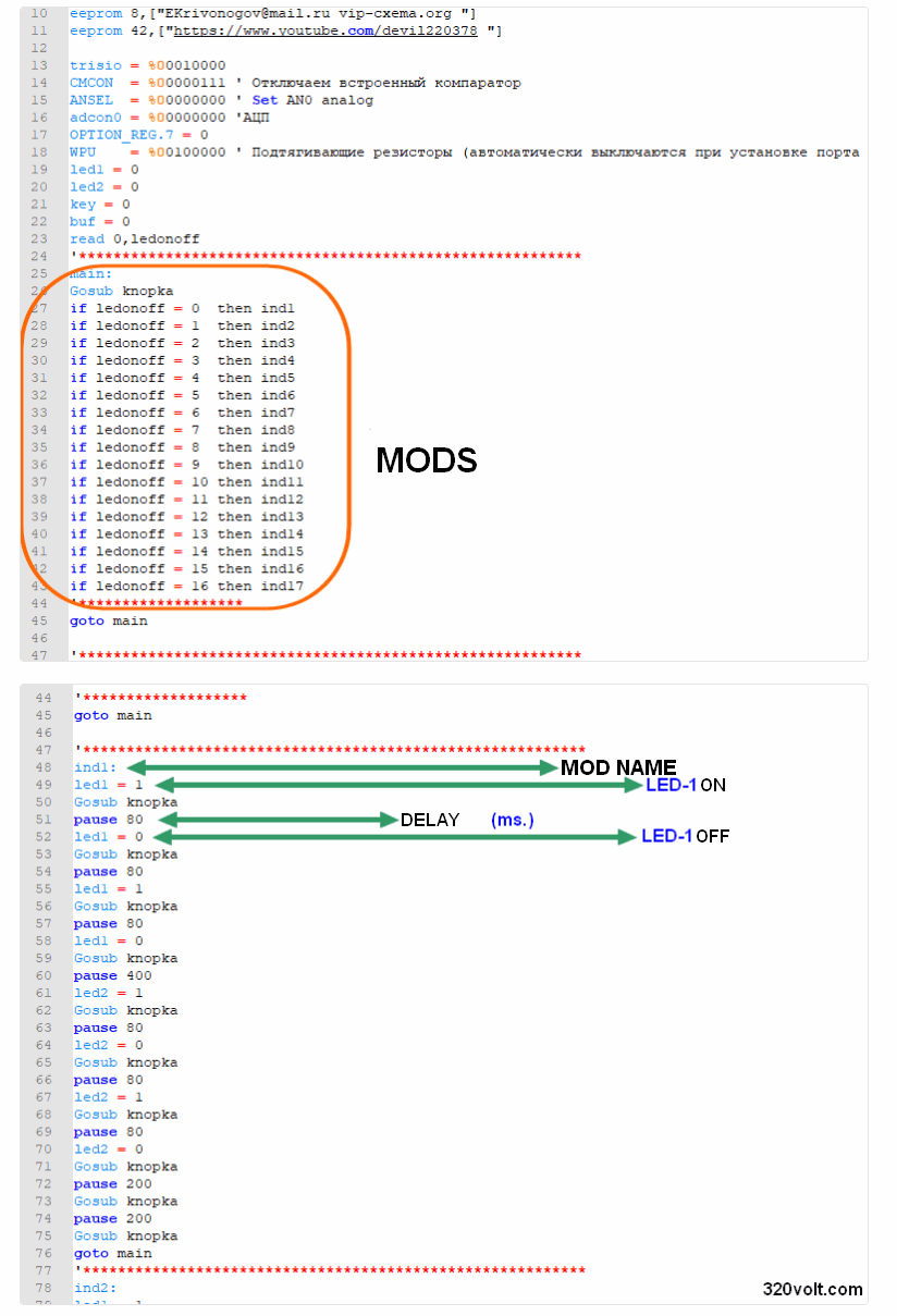
The Strobe Led Lamp circuit has 16 effect modes selected with the button built on the PIC12F675 microcontroller. Since the selected mode is stored in the integrated eeprom, the selected mode remains in memory when the power is cut. The source is Picbasic Pro software. You can adjust the lighting times of the LEDs and make different combinations.
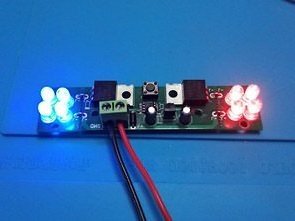
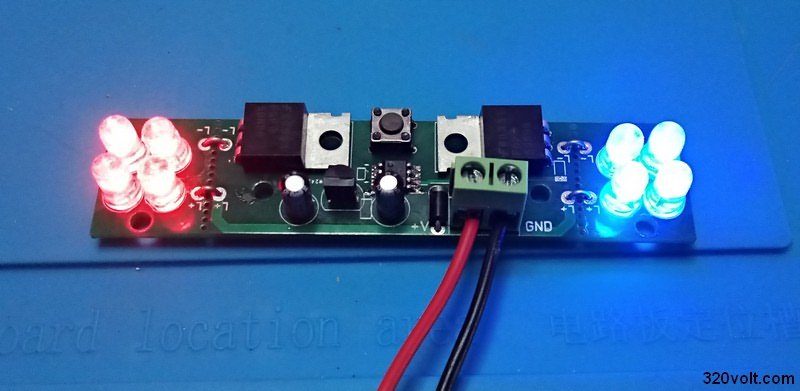
There are 4 LEDs on the left and right channel on the Led Flashing Lamp module. You can use high-power 5mm LEDs. PIC12F675 outputs are powered by 50N06 MOSFETs, so you can load up to 3 amps per channel.
Led Strobe Test
Contents
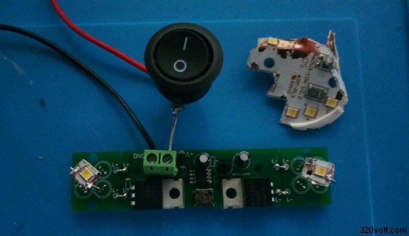
In the video, firstly, after the original software, the experiments I made with the modified software Strip LED and SMD 12V 1W LEDs seem very effective with 12V 1W leds, they say lightning effect on xenons or exactly that 🙂 When experimenting with 12V 1W leds, be careful I looked directly at the first attempt. gone 🙂 I cut the leds from the defective 10W LED lamp and used it because it is a cooler pcb, removing it with a soldering iron damages the lede directly.
Strobe LED Light Software Information
Led Strobe Flashing Circuit Diagram
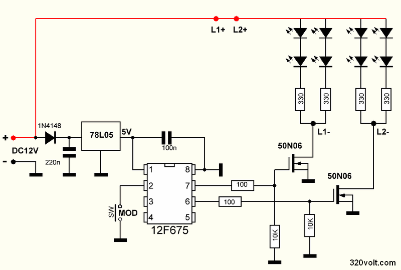
Since the microcontroller is used, the circuit is very simple, the PIC12F675 operating voltage is 5V and the 12V input 78L05 regulator integrated with it decreases to 5 Volts, the 1N4148 diode at the input of the integrated provides protection against reverse connection.
By the way, I have used electrolytic capacitors for 78L05 input and output filters, but I have reviewed a few products and fixed capacitors are sufficient for this circuit.
330-OHM was used for the standard 5mm transparent LEDs that you need to change according to the operating voltage and the current drawn. For example 3528 SMD LEDs that draw more current, 270-OHM can be used.
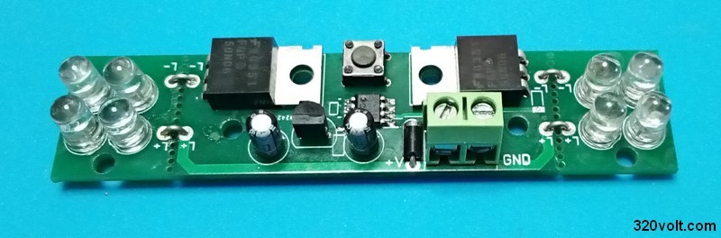
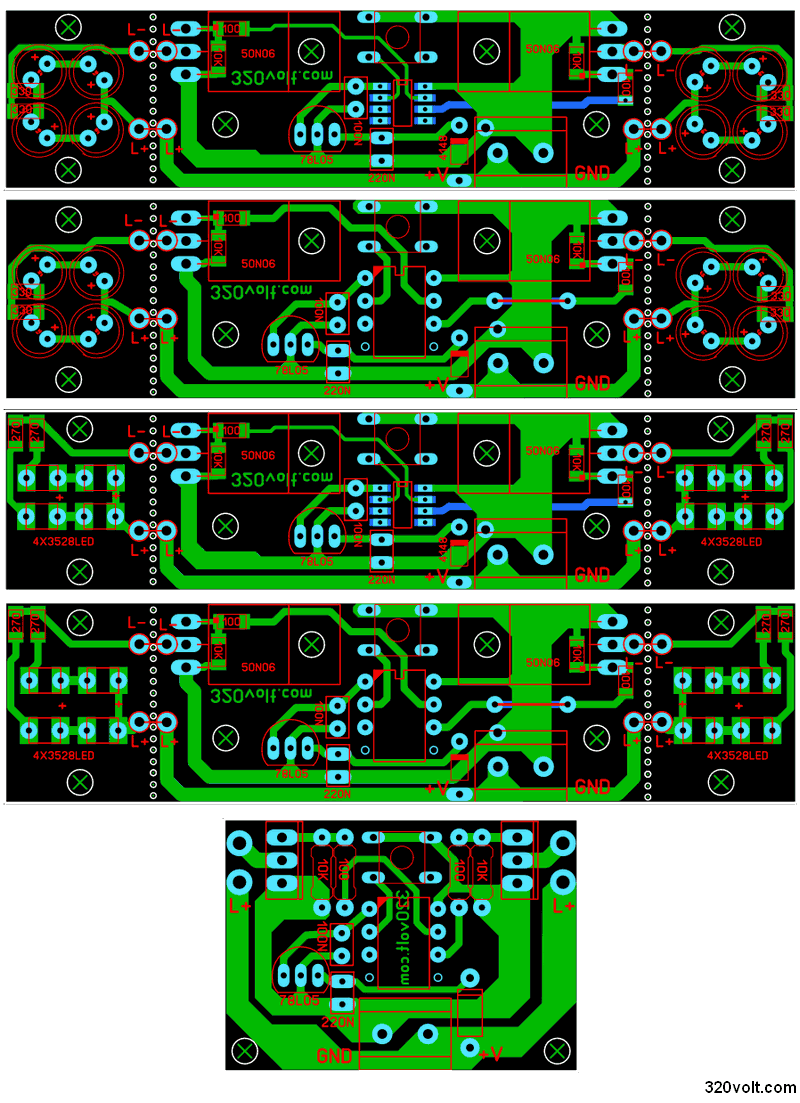
The PCB design of the Strobe Led module was designed as small as possible, and I prepared the PCB drawing of the PIC12F675 integrated version of the single layer DIP sheath for those who want to print and apply a few materials SMD type PCBs at home. In addition, I prepared PCB drawings for 3528 SMD LEDs. (Checked but not tried) In fact, I regretted that I used SMD type integrated when I did the application 🙂 At least if I made SMD transistors it would be smaller, but considering the power and cooler attachment events, there was a printed circuit like this, at least it worked flawlessly.
FILE DOWNLOAD LINK LIST (in TXT format): LINKS-27603a.zip
SOURCE: vip-cxema.org


