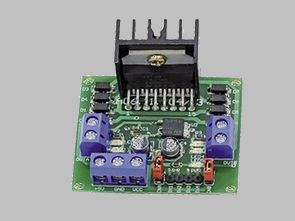
The L298 is an engine driver with two H-bridges. It can control two DC motors or one bipolar 4-wire stepper motor. Its main advantage is a large power supply voltage range (up to 46V) and high L298 maximum load currents: 2A continuous, 3A instantaneous.
In addition, the voltage has been applied to the CON1 connector, and the LED indicates “PWR”. LEDs2 … LED5 indicate the operation and direction of rotation of the attached motor. Starting the motor is done by supplying the logic “1” to the appropriate EN bridge of the bridge and the corresponding combination “0” and “1” to the IN1 … IN4 leads.
L298 motor driver schematic diagram

The L298 schematic diagram of the DC motor driver is shown in Figure 1. This is a typical L298 application. Schottky fast LEDs attached to the system outputs protect it from surges. The driver module is equipped with a voltage regulator 78M05 that supplies the digital part of the L298.
![]()
FILE DOWNLOAD LINK LIST (in TXT format): LINKS-25841.zip


Universal-Schaltkreis des DC-Motorsteuergeräts L298
Der L298 ist ein Motortreiber mit zwei H-Brücken. Es kann zwei DC-Motoren oder einen bipolaren 4-Draht-Schrittmotor steuern. Sein Hauptvorteil ist ein großer Versorgungsspannungsbereich (bis zu 46 V) und hohe L298 maximale Lastströme: 2A kontinuierlich, 3A unverzögert.
Außerdem wurde die Spannung an den Anschluss CON1 angelegt und die LED zeigt “PWR” an. LEDs2 … LED5 zeigen den Betrieb und die Drehrichtung des angeschlossenen Motors an. Das Starten des Motors erfolgt durch Anlegen der logischen “1” an die entsprechende EN-Brücke der Brücke und der entsprechenden Kombination “0” und “1” an die IN1 … IN4-Leitungen.
L298 Motortreiber Schaltplan