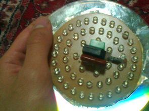
Transformerless circuit with 220V AC LED lamp is working . Half -polar LEDs 1 uF capacitor to run the transformer is used instead . High- voltage transformerless all LEDs are connected in series to study the drawing of printed circuit boards have prepared accordingly during installation of the LEDs + – do not confuse ends .
The amount of light lamps can be used as night work is not bad . Sink, small rooms , hallway lighting in places like enough. Use of LEDs that you have McD ( light power) not less than 2000 .. Transformerless about 55 pieces of white LEDs in LED lighting circuit is used.
CAUTION Transformerless Led Lamp Circuit is working with high voltage capacitor connection Observe caution + – If you connect the high voltage polarity may be large explosions before running the insured Power Line circuit , protective glasses and gloves
LED lighting circuit diagram of transformerless simple ;

Materials to be used on a few let me tell you first PCB drawing on the no insurance optionally not use it, but the insurance would suggest using at least 220V AC power cord can be plugged into the market small type glass fuses there .. .1 uf 400v capacitor value on the material 1uF writing as you can usually “105” author also operating voltage 250V AC or 275V AC can write you can use them + 20 Ohm resistor located only on departure will be at least 1W


Proteus ARES pcb circuit diagram of LED lighting:
FILE DOWNLOAD LINK LIST (in TXT format): LINKS-19961.zip


DC to DC Converter Circuit SG3524 SG3525 2X30V
Now I think about it in my head a lot of trouble while this circuit how I applied stunned quite a time now , huh now ha then say a kind I have not shared this day kısmetmiş Anyway my point was very useful to practice a lot of experience earned now DC DC Converters circuit TDA7294 , LM3886 , TDA7293 and so on. amplifier integrated in rather symmetrical + – 30v working with 100w … 200w amplifier 12 … 14 volts used to run .. especially cars suitable for use in a multi- amp circuit symmetrical supply voltage is driven with a 12v battery voltage turn the amp to make it available necessary
Found in PC power supply used transformer EI33 transformer output power , etc. ER35 . (formerly p3 in times of transformers on the EI33 writer , but after various codes were used EI33 core differences from none ) DC to DC converter circuit ATX Transformer reverse are using it as normal transformer “primary” high voltage driven portion output ‘re getting “secondary” low voltage output of the MOSFETs with ‘re driving
DC to DC Converter Circuit SG3524
Transformatorlose LED-Beleuchtung LED-Lampen-Schaltkreis
Transformatorloser Stromkreis mit 220V Wechselstrom-LED-Lampe arbeitet. Halbpolare LEDs 1 uF Kondensator zum Betrieb des Transformators wird stattdessen verwendet. Hochspannungstransformatorlos sind alle LEDs in Reihe geschaltet, um die Zeichnung der Leiterplatten bei der Montage der LEDs entsprechend zu prüfen + – Enden nicht verwechseln.
Die Anzahl der Lichtlampen kann verwendet werden, da Nachtarbeit nicht schlecht ist. Waschbecken, kleine Zimmer, Flurbeleuchtung an Orten wie genug. Verwendung von LEDs, die Sie haben McD (Lichtleistung) nicht weniger als 2000 .. Transformerless etwa 55 Stück weiße LEDs in LED-Beleuchtung Schaltung verwendet wird.
VORSICHT Transformatorloser LED-Lampenkreis arbeitet mit Hochspannungskondensatoranschluss Vorsicht beachten + – Wenn Sie die Hochspannungspolarität anschließen, können große Explosionen auftreten, bevor Sie den versicherten Power Line-Stromkreis, die Schutzbrille und die Handschuhe in Betrieb nehmen
LED-Beleuchtungsschaltplan von transformatorless einfach