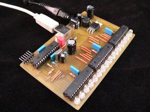
USB controlled RGB LED VU Meter PWM circuit 3 TLC5940 and one in 16 5mm RGB LED PIC18F2550 is being used. PC (Visual Studio C #) and microcontroller (Microchip pic c) have the source code of the software. USB Control software compatible with Windows 7 and Vista (XP does not support) also prepared by ExpressPCB circuit diagrams, printed circuit board’s files.
RGB LED VU Meter Circuit
Source: goo.gl/vSu5 RGB VU Meter Circuit Alternative link:
RGB VU Meter LED Circuit USB PWM PIC18F2550 TLC5940 ZIP File Password: 320volt.com


Low Noise Sine Wave Generator Circuit
Sine wave generator circuit tester jobs available in a variety BCXXX series transistors and passive components based on the 9 volt supply voltage of the circuit has a list of materials and PCB drawing.
Frequency range: 300 Hz, 1 kHz and 3 kHz Above 3kHz max. noise ratio (THD): 0.11%-1kHz, 0.23%-300Hz, 0.05%-3kHz Low power consumption: 4.5 mA Output voltage: 0 – 77.5 mV, 0 to 0775 V RMS
SineWave Generator Circuit