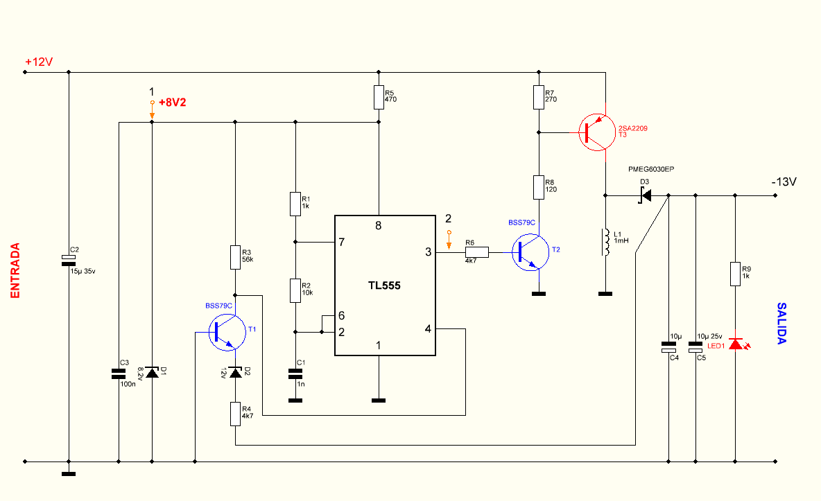
Buck Boost Converter circuit +12 V input voltage (10v. .25 there may be between)-13v as a favor from the (inverting) power 250mA optionally output voltage D2 zener diode changing can be increased or reduced (5v … 20v) circuit operating frequency of 12kHz pcb design (sprint layout) done according to the size quite small sMD components

FEATURES
Output current: 250mA without cooling (1A continuous and 2A instantaneous (with cooling)
Input voltage: 10 to 25V DC
Output voltage: -5 to -20V depends on the voltage of zener diode D2
Working frequency: 12kHz
Efficiency: 85%
555, the regulation of the output voltage is produced by the negative feedback loop (R4, D2, T1, R3), when the voltage reaches the threshold value, the zener diode D2 (can be freely selected to obtain different voltages), at this point a reset is generated in IC1 (pin 4), and the pulses at the pin 3 output of IC1 are shortened or extended according to the need, and in this case, the way to keep the voltage constant. Although no specific IC is used for inverters, the performance and stability of the circuit with different loads are high.
Project files and details of; Buck-Boost (Inverting) Converter


NCP1606B Power Factor Controller NCP1351B Switch Mode Power Supply
LCD TVs, monitors the use of devices is constantly evolving quite common image quality, additional features, etc.. is increasing with each passing day since the early days, one of the most important parts in solid SMPS inverter is still continually being developed, but I’ve seen most failures solid parts SMPS ..
This practice 180w pfc li (NCP1606B power factor pfc controller) inverter SMPS (NCP1351B Variable Off Time PWM Controller) circuit design from start to finish, schemes formulated and is described (in english) quite a useful document