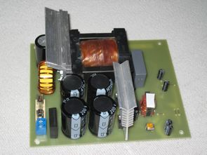
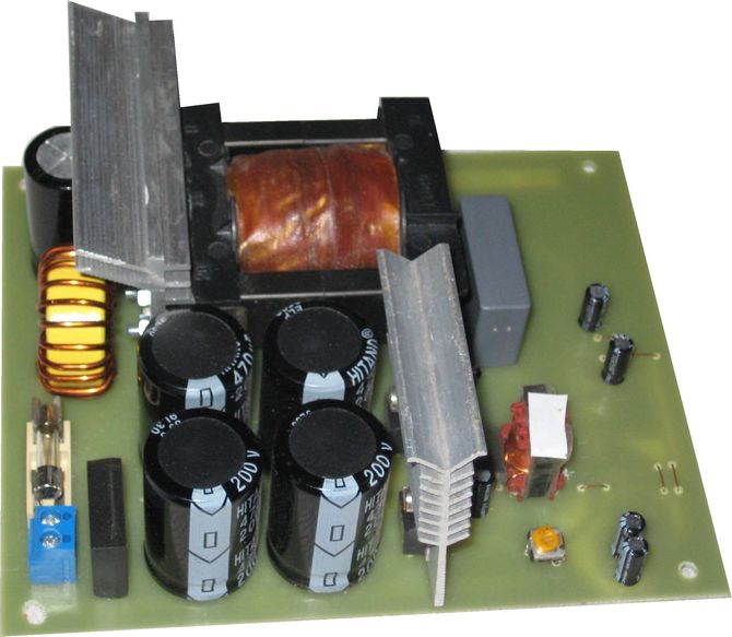
TL494 Audio amplifier switch mode power supply smps . TAS5611A Class D Amplifier Circuit Project The performance of the power unit should be about 400 Watts smps. The power source may be elected by the classic or switched. Because of the size and weight of the transformer of the classical sources is elected a switching power supply. This is a double acting the involvement of the switching transistors, which are controlled by the integrated circuit TL494
This place is connected to power transformer TR1. On the other side of the halfbridge output are power switching transistors MJE13009. Resistors R1 and R2 balance the leakage currents of the capacitors and thus help to keep an artificial center in the middle of the power supply voltage. Capacitor C5 are used to separate any dc components that arises from varying the switching of transistors. Diodes D3 and D4 are doing swells from the power of the transformer (ETD49) back to the filter.
Class D Amplifier Power Supply TL494 SMPS Circuit
Parallel-connected components composed of R11 and C8 partially compensates for the the inductive character of the load. Power transistors are driven from across the current excitation transformer TR2. Winding to the bases are attached so as to implement positive feedback.
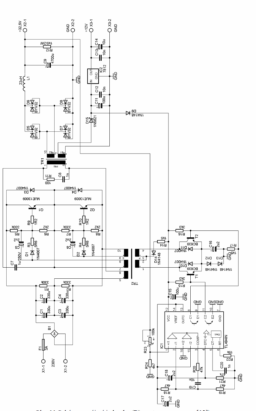
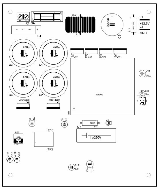
On the secondary side of the power transformer are two windings. As the main rectifier are used fast double diodes BYV32/200(2x8A). Voltage is filtered LC member composed of L1 and C9. Resistor R12 serves as a minimum load. The second secondary winding is rectified with Schottky diode, filtered capacitor C11. To obtain an accurate 12V voltage is used the regulator IC2.
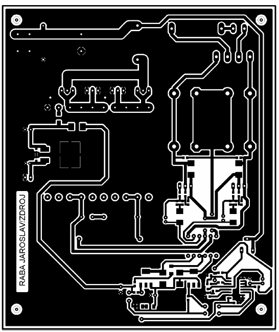
![]() tl494 smps circuit pcb schematic all files alternative links:
tl494 smps circuit pcb schematic all files alternative links:
FILE DOWNLOAD LINK LIST (in TXT format): LINKS-25554.zip


TAS5611A Class D Amplifier Circuit Project
The block diagram of the integrated circuit TAS5611A As mentioned above, the circuit contains 4 identical channels. The input signal is fed to pin INPUT_X. Signal continues into the feedback filter ANALOG LOOP FILTER and further to the input multiplexer the ANALOG INPUT MUX. In the block ANALOG COMPARATOR MUX occurs to compare the input signal with a reference voltage. The resulting PWM signal processing PWM RECEIVER. Followed by the procedure signal in the block CONTROL and timing of the signal in the block THE TIMING CONTROL. The last block is the exciter power transistors GATE-DRIVE, which is connected with the pin BST_X. This TAS5611A pin is used to connect a “bootstrap” capacitor. An auxiliary diode for the management of the way the “bootstrap” is integrated into the chip circuit. Power the voltage of half-bridges is connected between pins PVDD_X and GND_X. Supply voltage logic and control blocks in the circuit is supplied to pins VDD and GVDD_X. Power PWM the signal is led out pin OUT_X.
TL494 Klasse-D Verstärker Schaltnetzteil 390W 32V
TL494-Audio-Verstärker Schaltnetzteil smps . TAS5611A Klasse-D-Verstärker-Schaltung-Projekt Die Leistung vom Netzteil sollte über 400 Watt smps. Die Stromversorgung kann gewählt werden, von der klassischen oder geschaltet werden. Aufgrund der Größe und Gewicht des Transformators von den klassischen Quellen gewählt ist ein Schaltnetzteil. Dies ist ein doppeltwirkender die Einbeziehung der Schalt-transistoren, die gesteuert werden durch den integrierten Schaltkreis TL494 Schaltnetzteil