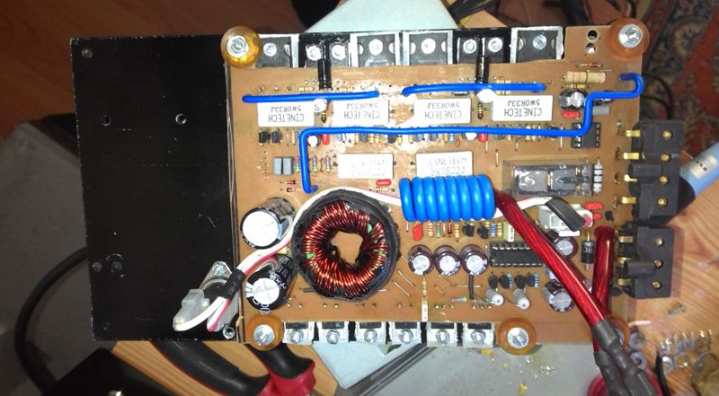
Car Amp IRFP240 IRFP9240 MOSFETs auto project from the forum @fatih_celebi24 comments below thanks for sharing it has be noted that sharing my brother’s @fatih_celebi24
Hello friends it has been a long time-tested the project we are sharing it with you auto amp.
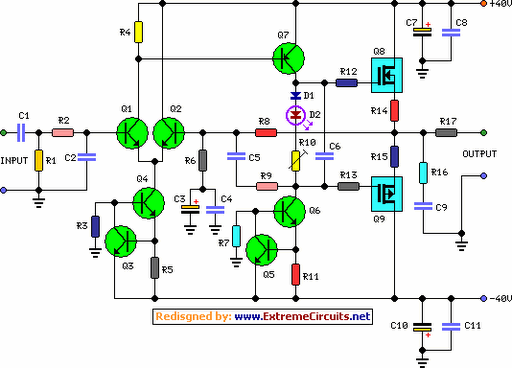
The circuit design for @master‘belongs to.
Solid and a working circuit. I have tried just the preamp-amp ICS in Izmir times because I couldn’t find it on the floor I wasn’t about to try. I stayed loyal to the original schema. I have made only minor changes.
I’m counting on the cooler feed REM normally closed 85C with thermal over-heat protection being added. the temperature of the cooler exceeds 85C thermal cut off the supply by opening the contacts at the time the back of the amp and the amp REM to the OFF position passes. When the level again falls below the 85c heat, thermal is located at the front position by closing the contacts of the amp.
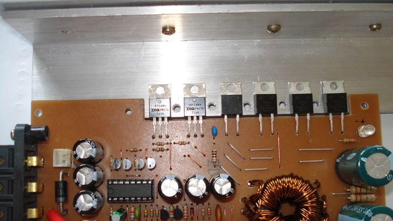
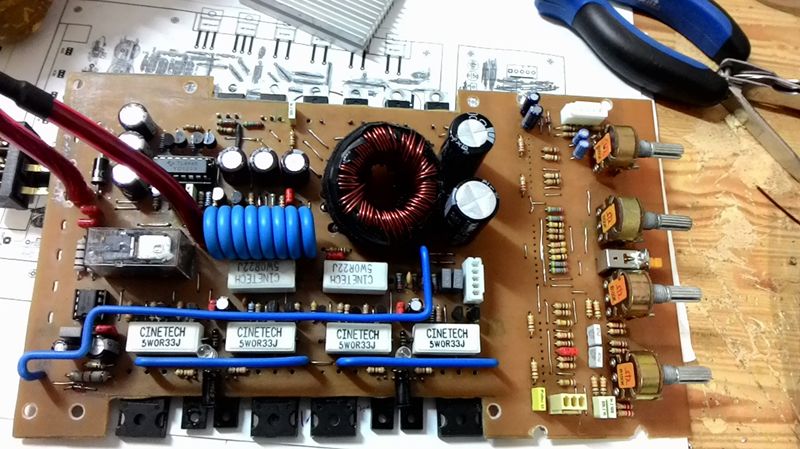
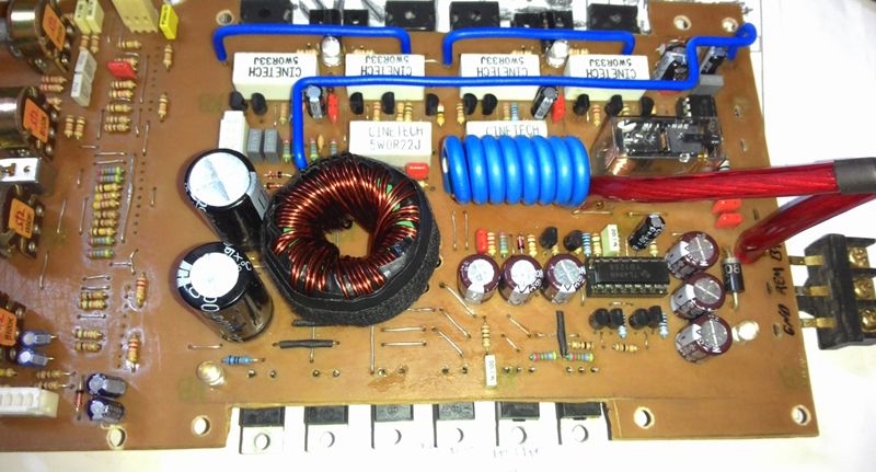
1W 330ohm resistors between the opamp output capacitors as the supply and providing supply was used instead of 330ohm 2W 1 W IRFZ44 instead IRFZ48 were used. IRFZ48 gate allows triggering transistor 100ohm 2W resistors on the Board, as amended, which is a euphemism for the amp I couldn’t find A43 a42 (mpsa42) has been replaced with. smps transformer winding should be done in a clockwise direction. in the original schema 2×12 11.7 14.4 V cc V vcc smps writes 2x20V I’ve been getting out in kind when I’ve been getting the amp Working Voltage max 2x50v 2×28, but the number of artirila is known to increase the power pour.
good luck in advance to friends will.
Amplifier features
the output: 60 watts RMS @ 8 ohms (1kHz sine) – 90W RMS @ 4 Ohm
the Sensitivity: 1V RMS input for 58w output with
a Frequency response: 30Hz to 20kHz -1dB
the Total Harmonic Distortion: @1KHz: 1W 0.003% 10W 0.006% 20W 0.01% 40W 0.013% 60W 0.018%
the Total Harmonic Distortion: @10KHz: 1W 0.005% 10 0.02% 20 0.03% 40W 0.06% 60W 0.09%

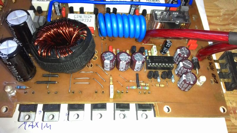
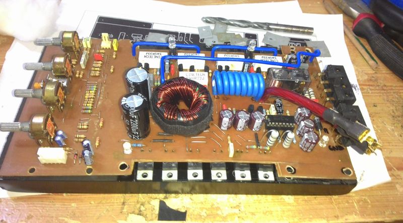

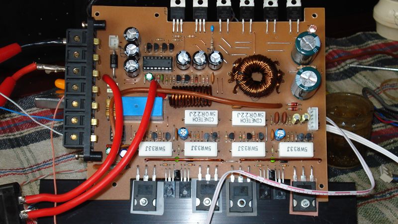


Note: stereo deck as stable in the previous design , performance and cost of this circuit at the request of a friend that I found appropriate in terms of auto amp. re-I’ve designed.. Smps as the Kenwood kac-716 standard scheme was used.
. 2×6 2×12 wrapped as kind of SMPS if primary secondary.
. Primary winding secondary winding in the output of the entrances IRFZ48N BY229-600 was used.
. Delay(delay times) that is becoming the standard as I founded on NE555 circuit has been used.
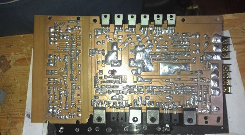
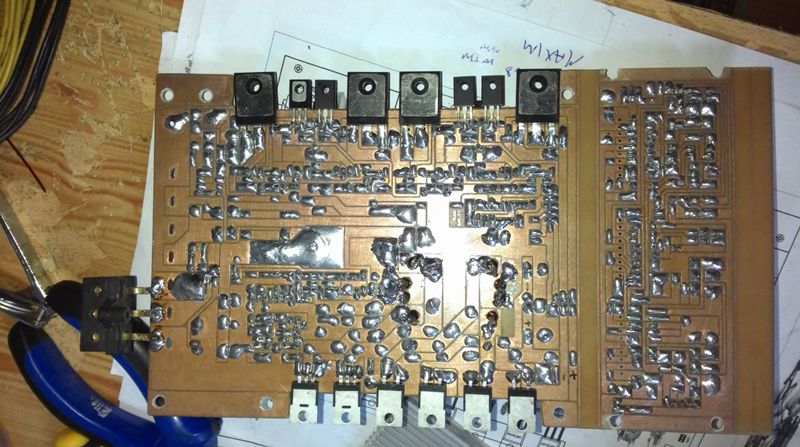
. Careful assembly and after the check, as usual trouble-free operation increased more.
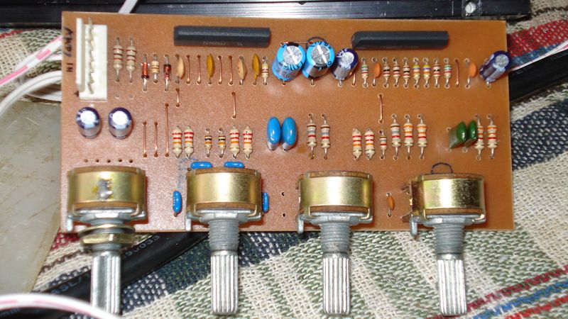
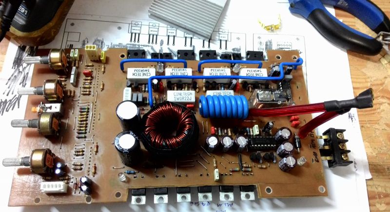
. Amp. I’m going to use 5-6 separate Tone Control at the entrance,xover ( lpf-hpf-full ) after you try the circuit, also I’m going to share with you again.
. You can use it on the front driver’s floor layout displayed in Pdf.
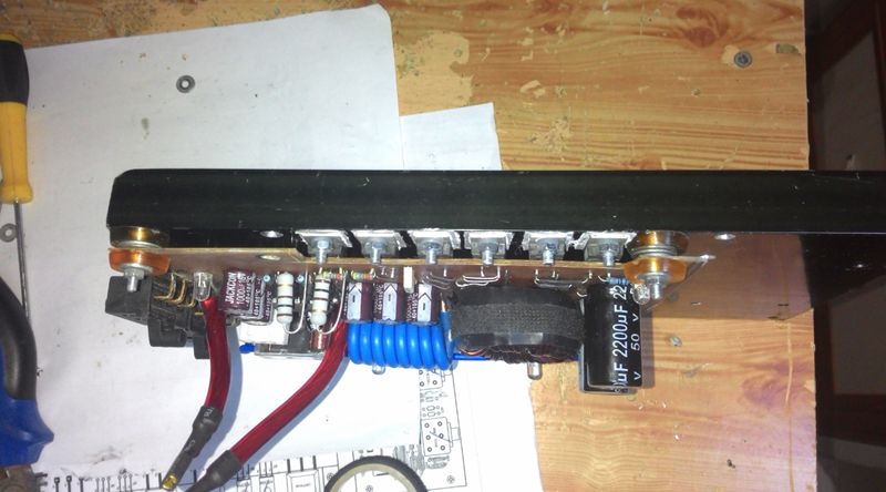
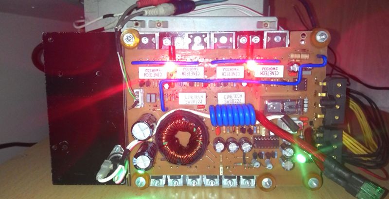
. Amp. my safe construction are in progress 🙂 the installation is completely finished I’ll share it when you take pictures if you request.
car amplifier circuit schematic, pcb all files:
FILE DOWNLOAD LINK LIST (in TXT format): LINKS-25430.zip
source: http://elektronikprojeler.com/index.php?topic=5834.15


Stereo-auto-Verstärker 180 Watt Kenwood kac-716 DC-DC-Wandler
Auto-Verstärker IRFP240 IRFP9240 MOSFETs Auto Projekt aus dem Forum @ fatih_celebi24 Kommentare unten danke für die Weitergabe hat es bemerkt, dass mein Bruder @ fatih_celebi24 teilen
Hallo Freunde, es ist ein lang erprobtes Projekt, wir teilen es mit Ihnen Auto Amp.
Das Schaltungsdesign für @ Master gehört dazu.
Solide und eine Arbeitsschaltung. Ich habe gerade den Vorverstärker-ICS in Izmir probiert, weil ich ihn nicht auf dem Boden finden konnte, den ich nicht ausprobieren wollte. Ich blieb dem ursprünglichen Schema treu. Ich habe nur geringfügige Änderungen vorgenommen.
Ich zähle auf den kühleren Feed REM normalerweise geschlossen 85C mit thermischen Überhitzungsschutz hinzugefügt. die Temperatur des Kühlers übersteigt 85C thermische Unterbrechung der Versorgung durch Öffnen der Kontakte zum Zeitpunkt der Rückseite des Verstärkers und der Verstärker REM in die OFF-Position passiert. Wenn der Pegel wieder unter die 85c-Wärme fällt, befindet sich die Thermik in der vorderen Position, indem die Kontakte des Verstärkers geschlossen werden.
1W 330 Ohm Widerstände zwischen den Operationsverstärker Ausgangskondensatoren als die Versorgung und die Bereitstellung der Versorgung wurde anstelle von 330 Ohm 2W 1 W IRFZ44 statt IRFZ48 verwendet wurden. IRFZ48 Gate ermöglicht Triggerung von 100 Ohm 2W Widerstände auf dem Board, wie geändert, was ein Euphemismus für den Verstärker Ich konnte nicht finden, A43 a42 (mpsa42) wurde durch ersetzt. Die Wicklung des SMPS-Transformators sollte im Uhrzeigersinn erfolgen. in der ursprünglichen Schema 2 × 12 11,7 14,4 V cc V VCC Smps schreibt 2x20V Ich habe in Art bekommen, wenn ich die Amp Arbeitsspannung max 2x50v 2 × 28 bekommen, aber die Anzahl der Artirila ist bekannt, dass die Erhöhung Macht gießen.