
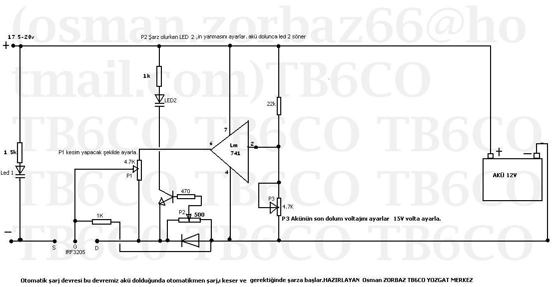
Very simple designs compared to complex Solar chargers but very useful. Loss is minimized as the first battery charge circuit LM741 opamp uses mosfet in the power control. Mosfet IRF3205 used
Author’s explanation about the 741 Opamp circuit;
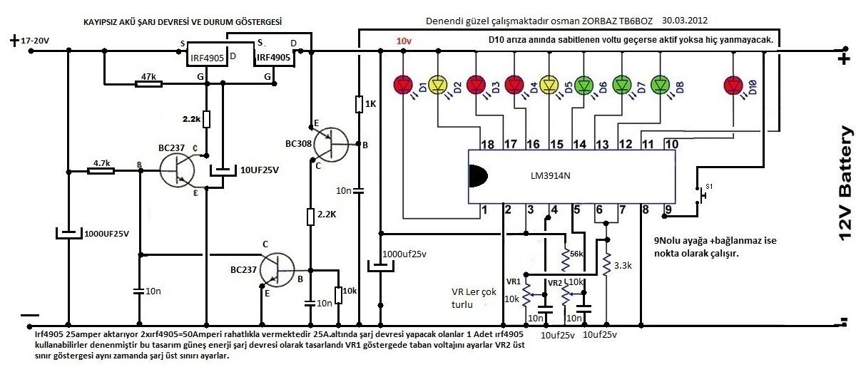
FRIENDS As you know, the charging circuits spend some of the current as heat in the transistor. This circuit transfers the current to the battery with very little loss. Since the energy coming from the solar panel is limited, I designed this circuit, it works very well. It can be used in the role I use. Opamp feet that are not shown in the diagram are empty
Adjusting the charging circuit; P1 will be adjusted to take the Mosquette to the cut. P2 Sets the LED to light while the battery is charging. When the battery is full, the led will turn off. P3 Battery max. 14.4v to be adjusted according to filling voltage
Note: The power of the diodes used in the circuits + or on the line should be determined according to the current drawn and the mosfet transistor should be connected to the cooler according to the current drawn.
Solar Energy Battery Charging Circuit Schematics


Circuits de charge de batterie d’énergie solaire simples
Conceptions très simples par rapport aux chargeurs solaires complexes mais très utiles. La perte est minimisée car le premier circuit de charge de batterie LM741 opamp utilise mosfet dans le contrôle de puissance. Mosfet IRF3205 d’occasion
Explication de l’auteur sur le circuit 741 Opamp;
AMIS Comme vous le savez, les circuits de charge dépensent une partie du courant sous forme de chaleur dans le transistor. Ce circuit transfère le courant à la batterie avec très peu de perte. Étant donné que l’énergie provenant du panneau solaire est limitée, j’ai conçu ce circuit, il fonctionne très bien. Il peut être utilisé dans le rôle que j’utilise. Les pieds Opamp non représentés sur le schéma sont vides
Réglage du circuit de charge; P1 sera ajusté pour amener la Mosquette à la coupe. P2 Règle la LED pour qu’elle s’allume pendant que la batterie est en charge. Lorsque la batterie est pleine, le voyant s’éteint. P3 Batterie max. 14,4 V à régler en fonction de la tension de remplissage
Remarque: La puissance des diodes utilisées dans les circuits + ou sur la ligne doit être déterminée en fonction du courant consommé et le transistor mosfet doit être connecté au refroidisseur en fonction du courant consommé.
Schémas du circuit de charge de la batterie à énergie solaire