Supply most laboratory power supplies maximum output current of 2 A to 3 A (Depending on model), while the output voltages usually up to 20 V or are more adjustable. Is, for example, at 6 V a current of 4 A needed is the power supply no longer able to deliver them, although the required performance far below the maximum output power of the Power supply is.
A remedy ensures the presented DC DC power converter, which simply between the power supply and the consumer with high current consumption to is off.
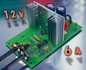
SG3524 DC DC Converter Circuit

The DC DC converter circuit works The basis of a step-down PWM regulator circuit and can accommodate up to 6 A of output current . provide At the laboratory power supply unit is a possible high voltage output (20 V to 35 V) is set, and the current limiting must be set to the maximum value.
The required output voltage is set on the DC DC power converter, wherein an adjustment of approximately 3V to 12V is available. Next an overcurrent protection circuit has the power converter also has an adjustable Current limit of 1.5A to 6A. As long as the current limit is active, this status is by means of the associated LED.

Source: http://www.elv-downloads.de/service/manuals/DCL100/61905_DCL100_km.pdf SG3524 Adjustable DC DC Converter Circuit alternative link:


Stepper Motor driver circuit with L297 L298
L298 L297 Motor Driver Robot, cnc, or you could use different control projects prepared with sprint layout PCB and the SPLA have been prepared with schema file.
L298 is an integrated H-bridge driver. Bipolar stepper motors are designed for driving. Max 2A/Phas could flow. The output signal is applied to the input phase upgrade to serve.
L297 L298 Motor driver