CCS C PWM Calculator Lately, I have been doing a lot of maths on my own because of my IR Obstacle detector design. Noticed a lot of people asking for help on configuring PWM using CCS C.
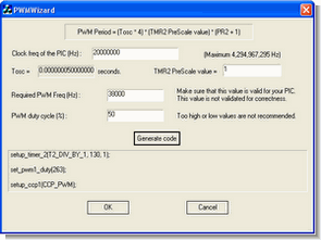
CCS C PWM Winzard

Why not make a tool to simplify the process for all ?
So I sat down today, fired up my Visual C++ IDE and got may hands dirty.
The attached EXE is hot from the compiler, and with lots of “hidden features”, of which even I may not be aware of.
PS : The default values are for setting up the PWM for 38Khz, 50% duty cycle on a PIC16F877A @20Mhz Just click on “Generate code” button to get ready code to copy paste in the CCS IDE
CCS C PWM Calculator program download :
CCS C PWM Calculator ZIP File Password: 320volt.com


AT89S52 DS1620 Thermometer Circuit (LCD Display)
This project gave ds1620’n given as a result of the digitally using AT89S52 microcontroller is a graphic display of temperature information of the LCD screen.
Moreover, the circuit ambient temperature when it reaches a temperature above 250C is no longer a red LED lighting in the same way as the ambient temperature drops below 250C, a green LED lights up to notify user intended. 12 MHz crystal clock oscillator circuit to set the clock oscillator is used.